Pin distribution and identification of integrated circuits
Time:2024-06-09
Views:62
The pin distribution law of integrated circuit is determined according to different packaging methods, and the pin number corresponds to the number in the integrated circuit diagram. Identifying the pin number of integrated circuit is of great significance to analyze the internal block diagram and working principle of integrated circuit, and to eliminate the fault of integrated circuit.
1. Pin distribution and identification of single row integrated circuit
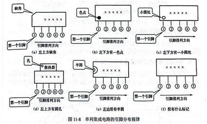
Figure 11-8 shows the pin distribution of a single-row integrated circuit. When identifying the pin distribution of a single row of integrated circuits, put the side printed with the plastic number up, facing itself, and put the pin down, as shown in Figure 11-8 (a), there is a missing corner on the upper left of the integrated block, as shown in Figure 11-8 (b), (c), there is a mark on the lower left of the integrated block. When there is no mark on the integrated block, place the integrated block front (the model is facing itself), from the left end to the right with 1, 2... pins, as shown in Figure 11-8 (f).


2. Pin distribution and identification of dual row integrated circuit
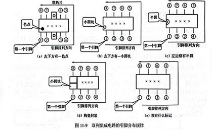
Figure 11-9 shows the pin distribution of a dual-row integrated circuit. The pins of a two-row integrated circuit are evenly distributed in two rows.
As shown in FIG. 11-9 (a), (b), (c), and (d), there is a mark on the left side of the integrated circuit. At this time, there is a pin 1 in the lower left corner. As shown in Figure 11-9 (e), there is no mark. At this time, the integrated block is placed directly, the model is facing itself, and the lower left corner is a pin 1, which is followed by 1, 2, and 3 pins in the counterclockwise direction.


3. Pin distribution and identification of four columns of integrated circuits
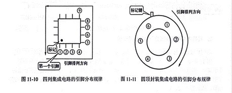
The pin distribution law of the four columns of integrated circuits is shown in Figure 11-10. From Figure 11-10, it can be seen that there is a mark on the integrated block, indicating the position of a pin, and then the number is clockwise.
4. Pin distribution and identification of dome packaged integrated circuits
The dome package integrated circuit uses a metal shell and looks like a triode, as shown in Figure 11-2, and the pin distribution rule is shown in Figure 11-11. As can be seen from Figure 11-11, the convex key is placed upward, taking the convex key as the starting point, and the clockwise direction is 1, 2, 3·· each pin.

|
Disclaimer: This article is transferred from other platforms and does not represent the views and positions of this site. If there is any infringement or objection, please contact us to delete it. thank you! |


