Introduction to the driving methods and characteristics of single-phase brushless DC motor drivers
Time:2023-11-05
Views:642
ROHM has over 220 models of motor driver ICs and has a strong market performance. The motor driver ICs covered include brushless DC motors, stepper motors, single-phase brushless DC motors, three-phase brushless DC motors (including high voltage), with a product lineup of various voltages, currents, and packages with high efficiency and reliability, as well as pin compatible products.

There are over 30 models of single-phase brushless DC motor driver ICs, and the single-phase brushless DC motor driver ICs support various driving methods and control technologies necessary for silence and high efficiency. The single-phase brushless DC motor driver IC product also has characteristic functions such as sine wave drive, lead angle control drive, wind resistance loss correction, I/O slope setting, back electromotive force jump improvement, standby function, etc.
Driving Methods and Characteristics of Single Phase Brushless DC Motor Driver
The following figure shows the driving mode and waveform of the ROHM single-phase brushless DC motor driver. The switch drive is a standard PWM drive, which has a faster switching speed and better efficiency compared to the output. However, the coil current also changes very quickly, which can have an impact on the mute performance. BTL drive is linear voltage driven through a bridged driver amplifier. Although noise can be reduced through soft switching, the efficiency is poor. PWM soft switch driving is achieved by setting the rise/fall range of the output as soft control, thereby reducing the distortion of coil current, reducing noise, and achieving efficient driving mode. Sine wave drive is a driving method that adds coil current adjustment function in PWM soft switch drive. Due to the ability to drive through coil current close to the sine wave, it is a driving method that can achieve extremely low noise.

Characteristics of ROHM‘s single-phase brushless DC motor driver
● Sine wave drive
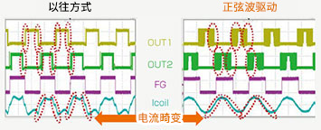
PWM soft switching is an effective method to reduce noise by reducing the conversion (rise/fall) of the output, utilizing Hall signals to generate waveforms. However, due to the temperature characteristics of the Hall signal, it may cause distortion of the coil current, resulting in increased noise.

The sine wave drive has the function of adjusting the coil current in the PWM soft switching range through external voltage, thus making the waveform of the coil current smoother and closer to the sine wave. It can further reduce the waveform distortion of the coil current, thereby achieving better silence.
● Leading angle control drive
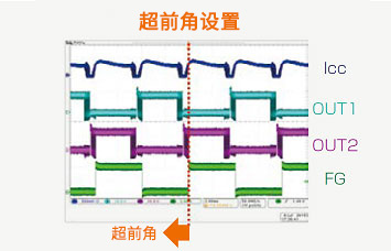
In order to obtain maximum torque, the phase of the driver output signal can be adjusted relative to the Hall signal to ensure that the phase of the magnetic field of the magnet (rotor) and the phase of the coil are at 90 degrees. The leading angle on the leading angle side can be set to a maximum of 22.5 degrees.

● Correction of wind resistance loss
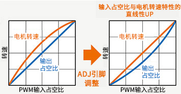
Wind resistance loss is the loss caused by the frictional resistance between the rotating part and air, etc. For example, in a fan motor, due to the characteristics of the motor, even if the output duty cycle relative to the input duty cycle is straight, the speed near the middle duty cycle may increase. Adjusting the linearity of the output duty cycle through the ADJ pin can improve the linearity of the motor speed and improve the accuracy of speed setting.

● I/O slope setting
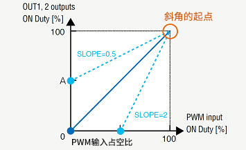
Equipped with the function of setting the slope characteristics of PWM input duty cycle and output duty cycle through the SLOP pin. This is a very convenient function for adjusting the characteristics of input and motor speed. The slope of the output duty cycle can be adjusted between 0.5 and 2. The following figure is an example of PWM input.

●Improvement of back electromotive force jump
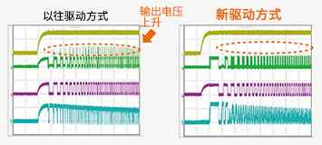
It can suppress the output voltage jump phenomenon when the speed changes during forward idle power on, reverse idle power on, locked rotor detection/recovery, and sudden torque input changes.

● Standby function
Reduce the power consumption of the motor driver when the motor stops. By setting the duty cycle of the PWM signal to 0%, the IC can be set to standby mode. Products equipped with standby function
|
Disclaimer: This article is transferred from other platforms and does not represent the views and positions of this site. If there is any infringement or objection, please contact us to delete it. thank you! |


