Design of LED Street Lamp Power Supply
Time:2023-09-26
Views:667
LEDs are more efficient than traditional bulbs and lights. They do not require preheating time to achieve brightness, which makes them better than fluorescent lamps. These devices can be assembled and used for lighting fixtures. With all the mentioned functions, LEDs are very suitable for street lighting applications.


This application note introduces a design guide for the 150W rating of LED street lighting. This application design consists of CRM PFC and LLC SRC, using FL7930B and FAN7621S to achieve high power factor and high power conversion efficiency. In order to verify the effectiveness of the application board and solution, a demonstration board 150W (103V/1.46A) AC-DC converter was implemented, and the results are presented in this application note. In CRM active PFC, the topology is a boost converter. This is because the boost converter can have continuous input current and can be manipulated through peak current mode control technology to force peak current to track changes in line voltage. FAN7930B is an active power factor correction (PFC) controller suitable for boost PFC applications operating in critical conduction mode (CRM).

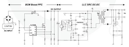
Figure 1 shows a typical application circuit, with a CRM PFC converter at the front end and a LLC SRC DC-DC converter at the back end. FL7930B and FAN7621S achieve high efficiency at medium power in 150W rated applications, with CRM and LLC SRC two-stage operation demonstrating performance. Compared with continuous conduction mode (CCM) boost PFC converters, CRM boost PFC converters can achieve higher efficiency at light and medium rated power. These benefits stem from the elimination of reverse recovery losses in boost diodes and zero current switching (ZCS). The LLC SRC DC-DC converter achieves higher efficiency than traditional hard switching converters. FL7930B provides controlled conduction time to adjust the output DC voltage and achieve natural power factor correction. The FAN7621S includes a high side gate driver circuit, a current controlled oscillator, a frequency limiting circuit, a soft start, and built-in protection. The high side gate drive circuit has the ability to eliminate common mode noise, ensuring stable operation and excellent noise resistance. The use of zero voltage switching (ZVS) can significantly reduce switching losses and improve efficiency. ZVS also significantly reduces switching noise, allowing for the use of small-sized electromagnetic interference (EMI) filters. The use of zero voltage switching (ZVS) can significantly reduce switching losses and improve efficiency. ZVS also significantly reduces switching noise, allowing for the use of small-sized electromagnetic interference (EMI) filters. The use of zero voltage switching (ZVS) can significantly reduce switching losses and improve efficiency. ZVS also significantly reduces switching noise, allowing for the use of small-sized electromagnetic interference (EMI) filters.
Basic operation of BCM PFC pre regulator
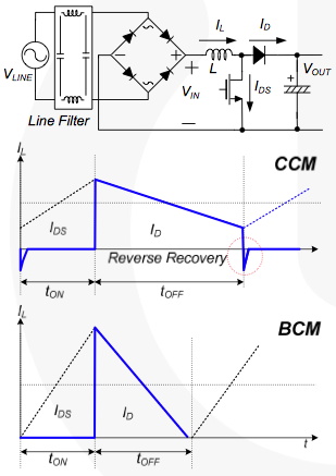
The widely used operating modes of boost converters are continuous conduction mode (CCM) and boundary conduction mode (BCM). These two descriptive names refer to the current flowing through the energy storage inductor of the boost converter, as shown in Figure 2. As the name suggests, the inductor current in CCM is continuous; In BCM, when the inductance current returns to zero, a new switching cycle begins, which is the boundary between continuous and discontinuous conduction operations. Although BCM operation has a higher RMS current in inductors and switching devices, it can provide better switching conditions for MOSFETs and diodes. As shown in Figure 2, it eliminates diode reverse recovery and does not require rapid diode recovery. The MOSFET also conducts at zero current,

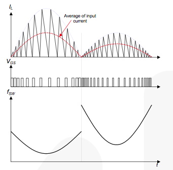
The basic idea of BCM PFC is that the inductance current in each switching cycle starts from zero, as shown in Figure 3. When the power transistor of the boost converter conducts for a fixed time, the peak inductance current is proportional to the input. Voltage. Due to the triangular waveform of the current; The average value of each switching cycle is proportional to the input voltage. In a sinusoidal input voltage, the input current of the converter follows the input voltage waveform with very high accuracy and extracts the sinusoidal input current from the source. This behavior makes the boost converter in BCM operation an ideal choice for power factor correction.

Figure 4 shows how the conduction time and switching frequency of MOSFETs vary with decreasing output power. When the load decreases, as shown on the right side of Figure 4, the peak inductor current will decrease with the shortening of MOSFET conduction time, thus increasing the switching frequency. Due to the serious switching loss caused by this under light load conditions and the possibility of excessive switching frequency operation during startup, the switching frequency of FL7930B is limited to 300kHz. Due to the fact that the design of filters and inductors for BCM PFC converters with variable switching frequencies should be carried out under frequency conditions, it is worth studying how the frequency of BCM PFC converters varies with operating conditions.
Considerations for LLC resonant converters
Attempts to achieve increasing power density in switch mode power supplies are limited by the size of passive components. Operating at higher frequencies can greatly reduce the size of passive components such as transformers and filters; However, switching loss has always been an obstacle to high-frequency operation. In order to reduce switching losses and allow high-frequency operation, resonant switching technology has been developed. These technologies process power in a sinusoidal manner and switch devices perform soft commutation. Therefore, switching losses and noise can be significantly reduced.

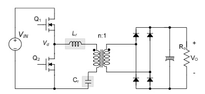
In order to overcome the limitations of series resonant converters, LLC resonant converters have been proposed. LLC resonant converter is an improved LC series resonant converter achieved by placing a parallel inductor on the primary winding of the transformer, as shown in Figure 6. When this topology was first proposed, increasing the circulating current on the primary side with parallel inductors was beneficial for circuit operation. However, it can effectively improve the efficiency of high input voltage applications, where switching loss is more dominant than conduction loss.
|
Disclaimer: This article is transferred from other platforms and does not represent the views and positions of this site. If there is any infringement or objection, please contact us to delete it. thank you! |


