Reduce the output voltage ripple of the flyback converter
Time:2023-09-20
Views:679
Flyback converters are widely used in low-power applications. The characteristic of this topology is that the input and output are isolated. When it is used in higher power output systems, the significant presence of voltage ripple becomes a problem. This application note discusses a method of reducing voltage ripple in flyback converters to achieve higher efficiency.


Flyback converters are widely used in low-power applications. The characteristic of this topology is that the input and output are isolated. In the case of its use in higher power output systems, the significant presence of voltage ripple becomes a problem. This application note discusses a method of reducing voltage ripple in flyback converters to achieve higher efficiency.
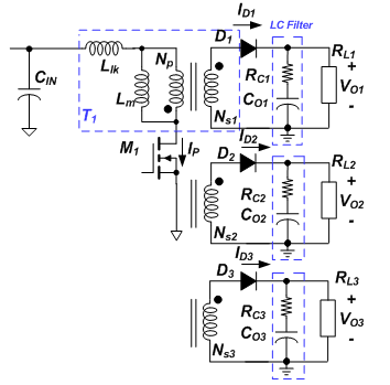
Flyback topology is a popular topology in offline charger applications because it can handle a wide input voltage range. Multiple outputs can be easily generated by using additional windings on the main transformer. Figure 1 shows a flyback converter with multiple outputs.

Flyback converter with multiple outputs
However, as the output power requirements increase, the voltage ripple on the flyback output capacitor will also increase. The traditional solution is to parallel multiple capacitors or capacitors with a single large capacitor to meet design specifications, which increases additional costs and increases the size of the adapter.
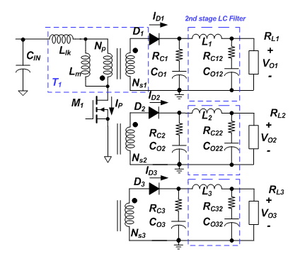
Alternatively, increasing the output stage of the LC filtering circuit can significantly reduce the output ripple. Figure 2 illustrates the flyback method using a second stage LC filter.

Flyback using a second stage LC filter
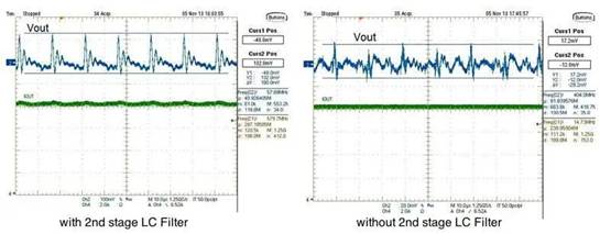
This is an application circuit shown in Figure 3. We have a flyback converter operating at 5V voltage and 8A load. The input voltage is 200V. There are two stages of output. A traditional filtering capacitor stage with a 5x1500uF capacitor. The second stage is an additional LC filter stage. For comparison, assuming L2=0uH and C2=1500uF - the output ripple is shown in Figure 4. In another example, assuming L2=1.35uH (C2=1500uF) - the output ripple shape is shown in Figure 5. Level LC filter, we can see that the output voltage ripple of Flyback converter can be greatly reduced. Adding L and C can reduce the need to parallelize so many capacitors to achieve lower output voltage ripple.

Application Circuit with Second Stage LC Filter
Output voltage ripple (VPK_PK=180mV) and load current (IOUT=8A) when using the second stage LC filter
VIN=200V, CO=5 × one thousand and five hundred μ F. RC=2.6m Ω, L2=0 μ H. C2=1500 μ F. RC2=13m Ω, Vo= 5V@8A
Reduce the output voltage ripple of the flyback converter
Output ripple without a second stage LC filter and output ripple without a second stage LC filter.
The output voltage ripple (VPK_PK=29mV) and load current (IOUT=8A) without a second level low-voltage filter.
VIN=200V, CO=5 × one thousand and five hundred μ F. RC=2.6m Ω, L2=1.35 μ H. C2=1500 μ F. RC2=13m Ω, Vo=5V @ 8A
|
Disclaimer: This article is transferred from other platforms and does not represent the views and positions of this site. If there is any infringement or objection, please contact us to delete it. thank you! |


