Current detection in sensorless brushless DC BLDC motor systems
Time:2023-09-19
Views:683
Other Parts Discussed in Thread: DRV8313, DRV8316
Have you ever designed, developed, used, or just played with any sensorless brushless DC (BLDC) motor control system? If so, you may already know the importance of continuously and accurately understanding the motor winding current. The rotating operation of the motor can be divided into different states, first the initial position detection or alignment, then the open loop state, closed loop state, and motor stop state. During all states, the controller continuously checks the current and voltage feedback of the motor to determine the next phase signal to be applied to the motor. The controller also uses current feedback to detect fault conditions and respond accordingly, thereby ensuring the stability and reliability of the motor system. We can say that current detection is the core and soul of any sensorless motor control operation.

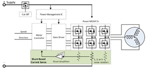
Figure 1: Typical Control Loop of a Sensorless BLDC Motor System
Current detection can be achieved through two main architectures:
1.Traditional method - external resistor current detection: This type of current detection can be achieved by adding a resistor in series with the motor phase (also known as inline current detection), or adding a resistor under the low side FET source (also known as current detection based on low side shunt resistor). In both cases, a voltage amplifier is used to measure the voltage drop across the resistor, and then an ADC (for motor commutation) or comparator (for monitoring) is used to feedback to the controller. In a three-phase BLDC motor system, you typically need three such resistors to measure the current in each winding. You can use two detection resistors to measure the current in both windings, and then calculate the current in the third winding in the controller. By combining all three detection resistors and measuring only one total current, the number of resistors can be reduced, but it will limit the types of control techniques you can use in the system. These resistors need to be power resistors that can handle full load motor current. The resistor will also have some significant power loss, resulting in hot spots on the circuit board.

Figure 2: Current detection architecture based on low side shunt resistor
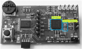
In the DRV8313 reference design example where a single shunt resistor is used to measure the total motor current, the resistor size is 3.05mm x 1.55mm. Compared to other components on the circuit board, a single shunt resistor occupies 13% of the space occupied by the three-phase integrated motor driver DRV8313. If three resistors are used to measure all winding currents, the resistors will occupy 50% of the total driver area on the circuit board!

Figure 3: DRV8313 Reference Design Circuit Board
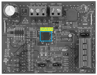
2.A New Method - Integrated Current Detection:In the DRV8313 reference design example where a single shunt resistor is used to measure the total motor current, the resistor size is 3.05mm x 1.55mm. Compared to other components on the circuit board, a single shunt resistor occupies 13% of the space occupied by the three-phase integrated motor driver DRV8313. If three resistors are used to measure all winding currents, the resistors will occupy 50% of the total driver area on the circuit board!

Figure 4: DRV8316 EVM circuit board
In the next section of this FAQ, we will discuss the system parameters using these two architectures, such as the transfer function and accuracy of current detection. Please continue to pay attention to the current detection in the sensorless BLDC motor system
|
Disclaimer: This article is transferred from other platforms and does not represent the views and positions of this site. If there is any infringement or objection, please contact us to delete it. thank you! |


