FM5841 Overview:
FM5841 is a high-end microwave radar sensor SOC chip developed by electronics, designed specifically for modern sensing needs. The chip operates in the frequency range of 5.725 to 5.825GHz and uses advanced Doppler radar algorithms to accurately and quickly recognize the movement of objects.
The main advantages of this SOC chip are its high integration and low power consumption characteristics. It integrates microwave transceivers, radar intermediate frequency amplification circuits, and other necessary digital modules, greatly simplifying the complexity of system design while ensuring excellent performance consistency and cost-effectiveness.
The working parameters of FM5841 can be adjusted through the standard I2C protocol. Its frequency adjustment is flexible and can be precisely adjusted within a specified range. The controllable characteristics of its gain ensure that the chip can maintain stable performance in high interference environments, reducing the possibility of co frequency interference and accidental contact with objects.
In addition, FM5841 adopts a wide voltage and low power architecture, providing customers with a wider range of power options, further expanding its application range. After combining with external MCU, a complete microwave radar sensing solution can be quickly constructed.
Overall, FM5841 not only supports the I2C protocol standard, but has also demonstrated its outstanding application potential in multiple fields such as smart lighting, smart home, and smart control, proving its competitiveness in the high-end sensing market.
FM5841 Features:
Working in the 5.8G ISM frequency band
Microwave Sensor Based on Doppler Effect
The sensing distance can be flexibly adjusted according to needs
Adopting mature CMOS technology, fully integrated with ultra-high cost-effectiveness
The chip is equipped with built-in LDO, which can effectively reduce interference from external power sources
Small size package QFN24 4x4x0.85 mm
Low power consumption, overall current of approximately 14mA
IF signal output, can be combined with self-developed intelligent induction algorithm
FM5841 Application:
Intelligent lighting
Smart Home
Home appliance control
Intelligent Sensing

FM5841 Structural diagram of the chip:

FM5841 PIN Foot definition:

FM5841 PIN Foot description:

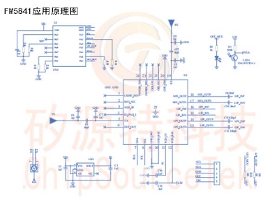
FM5841 Application schematic diagram:

1. The PI shaped network at the RX antenna end is used for matching input antennas. When the antenna impedance does not match, the network parameters can be adjusted to optimize RF performance;
2. The analog intermediate frequency output of the chip has two channels, namely LPF_ OUTP and LPF_ OUTN, one channel can be selected for ADC sampling, and the other unused IF signal pin can be suspended for processing;
3. After MCU sampling and simulating the intermediate frequency, it is necessary to filter out specific power frequency signals through algorithms to reduce the impact of power frequency on induction performance;
4. The typical power supply voltage of the chip is 5V. If the power supply voltage exceeds 5V, an additional LDO is required;
5. MCU configures the chip through I2C. If I2C wiring is longer, it is recommended to add 10k pull-up resistors on SDA and SCLK;


