精品国产sm全部网站免费_日韩精品毛片_推荐高清免费不卡网站_亚洲无码人成电影在线观看_一本伊大人香蕉久久網手機_福利视频你懂得_亚洲欧美曰韩在线_成年男女免费网站点播_成年人播放一级片高清_亚洲视频在线视频

Service Hotline: 13823761625

Support

Contact Us

You are here:Home >> Support >> Technology

Technology

How does the Boost circuit boost voltage? How is BUCK circuit depressurized?

Time:2024-06-14 Views:55

How is the Boost circuit boosted


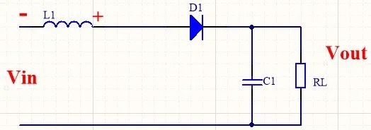
The basic Boost circuit is shown in the figure
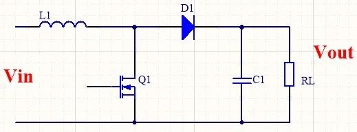

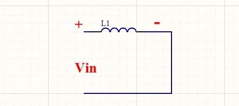
When Q1 is turned on, it is equivalent to the inductor shorting the input source Vin, and the inductor current will increase at a fixed slope, at which time the inductor is storing energy. The direction of inductance voltage is positive left and negative right.

At this time, Vin=L* (△i/△t pass),

Reduce to△i=(Ui*T*D)/L……①

Where △t is the opening time of Q1, T is the switching period, and D is the duty cycle.

When Q1 is disconnected, the inductor current continues to follow the original direction because the inductor current cannot be mutated, and the inductor current is bound to decrease due to the increased impedance in the closed-loop path (there is an output capacitance in the path). The inductance to prevent its reduction will generate the reverse electromotive force VL. At this point, the voltage on the output voltage C1 is equal to the reverse electromotive force VL plus Vin on the inductor.

It can be understood as the original one battery, and later became two batteries in series. Therefore, the output voltage is higher than the input voltage, and the voltage boost is achieved.


In this case, L* (△i/△t break) + Vin = Vout

Reduce to△i={(Vout-Vin)*(T - T*D)}/L……②

△t break is Q1 break time

At the moment when Q1 is turned off, the inductor current cannot change, so the current △i at the moment of turning on and turning off is equal.

According to ①② we can get Uo/Ui=1/ (1-d), duty cycle D < 1, so the output voltage is higher than the input voltage.

How is BUCK circuit depressurized
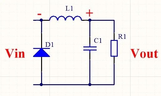

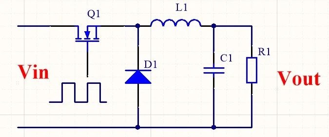
The basic BUCK buck circuit is shown in the figure


When Q1 is turned on, because the diode is reversed off, the current flows directly through the inductor to the load. The direction of inductance voltage is positive left and negative right. As shown below.


In this case, the voltage at both ends of the inductor is

VL=L*(△i/△ton)=(Vin - Vout)

Where, △ton is the opening time of Q1.

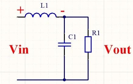
When Q1 is disconnected, the diode provides a loop for the inductive current. Since the inductor current cannot be mutated, the inductor current continues along the original direction, the current path is L+→C1 (R1)→D1→L1-, and the voltage direction is positive to the right and negative to the left. As shown below.
At this time, the voltage at both ends of the inductor is equal to the load voltage,

L*(△i/△toff)= -Vout……②

Where △toff is Q1 disconnect time, and the minus sign indicates that the voltage direction is opposite to the original direction.

Since the average voltage on the inductor at steady state is zero (if it is not zero, then the voltage on the inductor will keep falling or keep rising)

therefore

Von*Ton+Voff*Toff=0

namely(Vin - Vout)*Ton+(-Vout)*Toff=0

Simplify to:

Vout={Ton/(Ton+Toff)}*Vin
Vout=D*Vin

Where D is the duty cycle.

The above calculation is in the case of continuous inductance current.

When the inductor current is discontinuous, there will be a phenomenon of zero inductor current during Toff, which is equivalent to a larger denominator, that is, a larger duty cycle, so the output voltage is larger than when the inductor current is continuous.

Sum up:The output voltage of BUCK circuit is mainly determined by the duty cycle ratio. The larger the duty cycle ratio, the larger the output voltage, and the smaller the duty cycle ratio, the smaller the output voltage.


    Disclaimer: This article is transferred from other platforms and does not represent the views and positions of this site. If there is any infringement or objection, please contact us to delete it. thank you!
    矽源特科技ChipSourceTek