CCM mode and DCM mode of Boost circuit
Time:2024-05-16
Views:127
The Boost circuit can operate in current discontinuous mode (DCM) and current continuous mode (CCM). CCM working mode is suitable for high-power output circuit, and the inductance current needs to be kept in continuous state, so the characteristics are analyzed according to CCM working mode. Regardless of the topology, the definition of CCM and DCM is the same.
According to the actual value of inductor current at the beginning (end) of each switching cycle in the stable state of the converter, the working mode of the converter is determined:
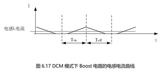
? In the steady state, if the current returns to zero in each cycle, it is intermittent conduction mode (DCM);
If the current returns to a value greater than 0, it is called continuous conduction mode (CCM);
If it returns to zero exactly at the end of the cycle, it is called the critical continuous mode (BCM), and the converter is free to choose the DCM or CCM equation when operating in BCM.
According to the previous analysis, we can know that the average current on the inductor is actually determined by the load, because the output voltage is certain, the smaller the equivalent resistance of the load, the greater the average current IL (avg) flowing through the inductor; The ripple current on the inductor is related to the inductance value when the input and output voltage are determined. When the average current is large enough, the current of the inductor is in a steady state, continuously changing around the average current in the form of a ripple. When the load changes, the current changes, which is reflected in the average current change of the inductor. As shown in Figure 6.16, the waveform moves up and down as a whole, and the amplitude of the circuit ripple size does not change.
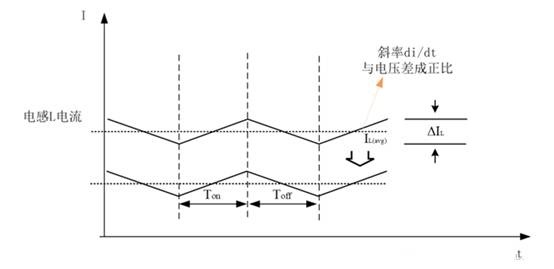

FIG. 6.15 Curve of ripple current increasing as inductance decreases
In the normal working process of the circuit, if the minimum value of inductor current is greater than 0A, that is, the inductor is in a steady state of continuous output current, but there is a regular ripple fluctuation, then it is a CCM mode, as shown in Figure 6.15. In order to ensure the continuity of the current, the inductor current should meet the following requirements:
At the time, the Boost circuit was operating in continuous on-mode (CCM).
At that time, the Boost circuit was operating in critical on-mode (BCM).
At that time, the Boost circuit was operating in discontinuous on-mode (DCM).
1. CCM mode
As shown in Figure 6.16, CCM is analyzed in two stages: switch on and switch off.
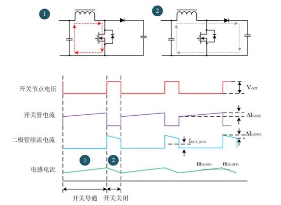

Figure 6.16 Two states of Boost circuit in CCM mode
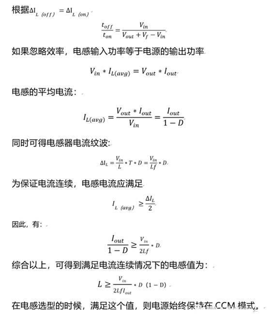
When the switching tube S is on and the diode D is off, the current flowing through the inductor L and the switching tube gradually increases, and the voltage at both ends of the inductor L is Vin, taking into account the on-voltage drop Vs of the MOSFET S pole to the common end, that is, Vi-Vs. At ton, the current through L increases in part △ILon. boost converter CCM/DCM boundary condition The boost boundary condition of CCM/DCM means that the inductor current during the switching cutoff period decreases from the maximum value exactly to zero, and once the current value is zero, a switching cycle begins. At this time, the average inductance current can be expressed as:


The voltage drop Rds (on) when the switch tube is on and the voltage drop of other resistors or wires on the line can be ignored.
When the switching tube is off, diode D is in the on-state, the energy stored in the inductor L is provided to the output, the current flowing through the inductor L and diode D is in a reduced state, let the forward voltage of diode D is Vf, when the switching tube is off, the voltage at both ends of the inductor L is Vout+ VF-VIN, and the current reduction part △ILoff meets the following formula.

Vf is the forward voltage drop of the rectifier diode, the fast recovery diode is about 0.8V, and the Schottky diode is about 0.5V. In the steady state of the circuit, that is, from the continuous current to the maximum output.

2. BCM
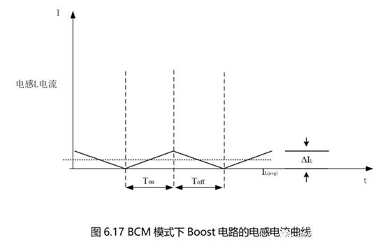
Like Buck circuits, BCM is a critical state, equivalent to the inductance of exactly 0A. BCM is the CCM-DCM critical mode. In essence, BCM is more like a special case of CCM, and the waveform is also a steady state like CCM, as shown in Figure 6.17.

3. DCM
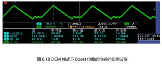
After the switch is turned off, the inductor is in a charge that releases energy. When the current of the inductor continues to discharge, once it reaches 0A, no energy will continue to be released and 0A will be maintained. At this time, the output current depends on the output capacitance to maintain, and the current of the inductor is shown in Figure 6.18.

The waveform actually tested is shown by the green curve in Figure 6.18.

|
Disclaimer: This article is transferred from other platforms and does not represent the views and positions of this site. If there is any infringement or objection, please contact us to delete it. thank you! |


