Design of DC-DC chip FB divider resistor circuit
Time:2024-04-07
Views:183
In the use of DCDC chip circuit design will encounter the problem of calculating the partial voltage resistance, the following is a brief introduction to how to calculate
The output voltage of the following circuit is Vout=1.8V Query the VFB voltage of the chip
 VFB voltage VFB=0.5V is found on the datasheet
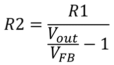
The calculation formula is as follows R1 usually uses adjustable resistors, 50K or 200K, etc. After R1 selects the value, R2 is calculated as follows:

The output voltage of the following circuit is Vout=1.8V


The calculation formula is as follows


|
Disclaimer: This article is transferred from other platforms and does not represent the views and positions of this site. If there is any infringement or objection, please contact us to delete it. thank you! |


