Use of integrated operational amps
Time:2024-04-01
Views:193
I. External lead of integrated op amp (pin)
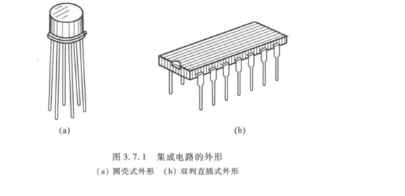
At present, the common packaging methods of integrated OP amPs include metal shell package and dual in-line package, as shown in Figure 3.7.1, with the latter being the majority. Dual in-line type has 8, 10, 12, 14, 16 pins and other types, although their external lead arrangement is increasingly standardized, but the manufacturers are still slightly different. Therefore, before using the operation amplifier, you must consult the relevant manual and identify the pins for correct connection.
At present, the common packaging methods of integrated OP amPs include metal shell package and dual in-line package, as shown in Figure 3.7.1, with the latter being the majority. Dual in-line type has 8, 10, 12, 14, 16 pins and other types, although their external lead arrangement is increasingly standardized, but the manufacturers are still slightly different. Therefore, before using the operation amplifier, you must consult the relevant manual and identify the pins for correct connection.

Before using the operation amplifier, it is often necessary to use a simple test method to judge its quality, such as using the middle stop of the multimeter resistance (" × 100Ω "or" ×1kΩ "stop to avoid excessive current or voltage) to test whether there is short circuit and open circuit phenomenon on the care foot. If necessary, test equipment can also be used to measure the main parameters of the operational amplifier.Three, zero and set the bias voltage
3.Three, zero and set the bias voltage
Due to the existence of offset voltage and offset current, the output is often not zero when the input is zero. For the operation amplifier without automatic zero stabilization measures, it is necessary to add a zeroing circuit, so that the output is zero when the input is zero.
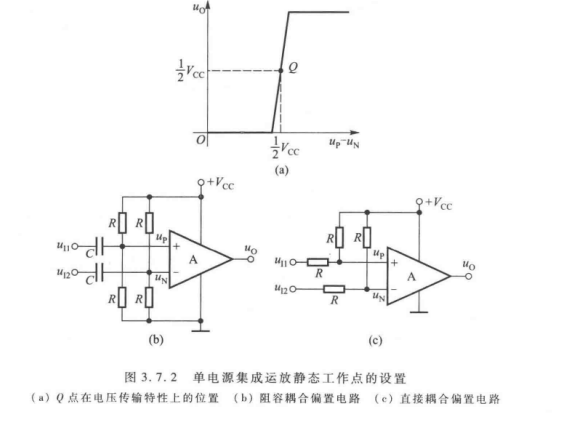
For a single-supply opamp, it is often necessary to add a DC bias voltage at the input end and set a suitable static point to amplify the positive and negative signals. For example, in order to make the amplitude of the change of the positive and negative signals the same, the Q point should be set at the midpoint of the integrated op amp voltage transmission characteristic, that is, Vc/2, as shown in Figure 3.7.2(a).

4. Eliminate self-excited oscillations
In order to prevent the circuit from generating self-excited oscillation (1) and eliminate the influence of each circuit due to sharing a power supply, the decoupling capacitor should be added to the power supply end of the integrated op amp; "Decoupling" refers to removing the connection, generally decoupling capacitors use a large capacity and a small capacity capacitor in parallel in the positive and negative poles of the power supply.
|
Disclaimer: This article is transferred from other platforms and does not represent the views and positions of this site. If there is any infringement or objection, please contact us to delete it. thank you! |


