How to detect Type-C connection and direction
Time:2024-03-26
Views:210
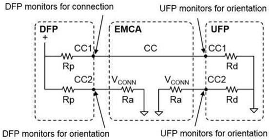
The specification describes how the Type-C upstream port (UFP) applies pull-down resistors (R d) on the configuration channel pins CC1 and CC2 to indicate that it is a device, and the Type- C downstream port (DFP) needs to have pull-up resistors (R p) on CC1 and CC2. The generated resistance divider is used to determine the connection and separation of Type-C equipment. The direction of the Type-C cable plug in each socket is easy to determine, because only one of the two CC pins is connected on the cable.


Electronic Marking Cable Assembly (EMCA) is a cable that needs V CONN to supply power to the marking electronic equipment in the cable. These EMCA expose the R a terminal resistance on the V CONN pin of the Type-C plug. There is no electronic equipment inside the non-electronically marked Type-C cable, and there is no need for V CONN power supply. These non-EMCA cables leave the V CONN pin suspended on the Type-C plug.
The R p and R d terminal resistors on the CC pin of the socket can detect the connection event and identify the direction of the Type-C plug in the socket. DFP and UFP monitor the two CC pins on the Type-C socket to know the voltage change of their unterminated voltage, so as to detect the connection event. UFP also monitors V BUS as the second indicator of DFP connection. Both DFP and UFP can determine the direction of Type-C cable plug at their respective connection ends. This is possible because only one CC pin is connected by cable. After detecting the connection and direction, the other CC pin is reused as a V CONN by DFP. If the R a terminal resistance is detected, it supplies power to the electronic equipment in the USB Type-C EMCA plug.
|
Disclaimer: This article is transferred from other platforms and does not represent the views and positions of this site. If there is any infringement or objection, please contact us to delete it. thank you! |


