A Scheme of Brushless Motor BLDC Square Wave Drive
Time:2024-01-04
Views:411
The article mainly introduces in detail the method of BLDC motor square wave driver, which is based on the position of the rotor to connect power to the matching winding. At each moment, only two interconnections in the motor stator winding are supplied, so that each phase winding can be turned on or off at an angle of 120 degrees. At one electrical angle (360 degrees), six different forms of encouragement can be completed in a cycle time, hence it is called a waveform Drive or six step commutation control.
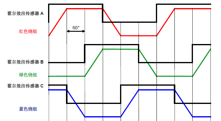 Red winding: Phase A Green winding: Phase B Blue winding: C
 (2) Basic principle of six step commutation without sensor control
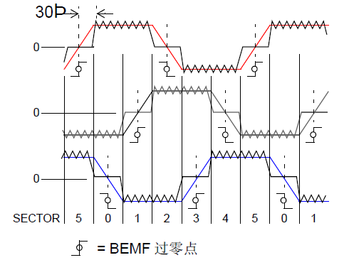 Bright red: A-phase BEMF, emerald green: B-phase BEMF, dark blue: C-phase BEMF
 Above is the basic principle of brushless DC motor waveform driver.
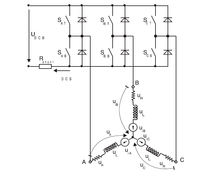
The following diagram is a schematic diagram of the three-phase bridge drive of a brushless DC motor:

Figure 1: Partial output power and system architecture diagram of brushless DC motor
The six step commutation driver is a common method of three-phase Y-shaped connection for BLDC motors. In the six step switching, the BLDC motor adopts a two-phase working mode, with only two phases conducting and the other phase breaking at any time. The selection of which two-phase winding to turn on or off is determined by the position of the rotor, and the sensing of the rotor can be obtained by a phase sensor or a position observer to obtain both the existing inductor waveform driver and the non inductor waveform driver.
(1) The basic principle of six step commutation operated by Hall sensors (120 degree spread)

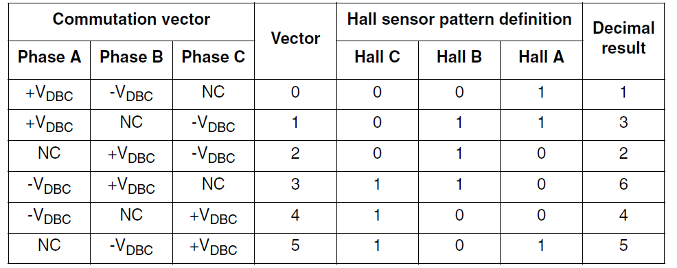
HallA, HallB, and HallC are three Hall sensors installed in different parts of the motor, used to check the relative polarity in the rotor area of the three windings (A/B/C). During the entire operation of the motor, when the forward magnetic induction line crosses the Hall sensor, the sensor outputs "1", and vice versa, outputs "0". Because three Hall sensors are uniformly installed at a 360 degree electrical angle, when the motor runs for one electrical equipment cycle time (360 degrees), each Hall sensor‘s pulse signal will generate 2 rotations, a total of 6 pulse signal rotations. Because the sensors are evenly distributed, each rotation is exactly 60 degrees apart from each other, which is the electrical angle of the motor‘s second commutation phase distance. According to the continuous loading of different pulse signals from the Hall sensor, the rotation time is determined, and then the relative winding is powered on, so that the motor can operate stably.


As shown in the figure, the self induced electromotive force working voltage on the unconnected power phase winding is checked in each section (60 degree electrical equipment angle). When the self induced electromotive force working voltage passes through the "center" or "zero crossing", it is detected that a zero crossing occurs. The control system learned that the rotor is currently located at the center of the 60 degree electrical equipment angle range and has a spacing of 30 degrees for the next phase change of the electrical equipment angle. The timer records the time for each section (60 degree electrical equipment angle) as T60. When zero crossing is detected, the timer will be loaded with a preset value of half of T60. The timer generates a request timeout, which will cause a termination and complete the next phase change. This type of control measure is called sensorless operation of BLDC motors.
There are various ways to inspect the position of the rotor for sensorless operation of BLDC motors. For example, BEMF measurement method, magnetic flux measurement method, various system software data signal observer method, data signal introduction method, etc. At present, the most commonly used method is the BEMF method, which completes commutation by checking the zero crossing point of the self induced electromotive force of the disconnected phase. Other phase sensorless control measures will be discussed in the subsequent chapter directory.
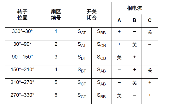
The following table shows the three-phase bridge driver of a DC brushless motor (as shown in Figure 1), the power switch situation matched with the six step commutation in each electrical equipment cycle time (360 degrees), and the correlation between the direction of current and the rotor position.

|
Disclaimer: This article is transferred from other platforms and does not represent the views and positions of this site. If there is any infringement or objection, please contact us to delete it. thank you! |


