To be honest, many people have a wrong understanding of the tolerance of ceramic capacitors!
Time:2023-11-09
Views:611
For ceramic capacitors (commonly known as MLCC, also known as multilayer ceramic capacitors), the term "tolerance" refers to the deviation of the equipment capacitance from the nominal value, which is only caused by changes in the manufacturing process. Tolerance is measured under strictly defined testing conditions, and this process is specially designed to exclude the influence of other factors on the measurement capacitance of specified equipment.

Understanding "tolerance" as an overall range is a common misconception. Some people believe that regardless of the measurement conditions, the measured value should be within the specified tolerance range of the nominal value. Many products have very stable characteristics, making it easy to overlook this difference; Ceramic capacitors do not belong to this category of products. (Those ceramic capacitors based on Class 1 dielectrics are exceptions; please refer to this post for an explanation of dielectric classification.)
However, the capacitance characteristics of many ceramic capacitors based on Class 2 and Class 3 dielectrics are extremely unstable, so arbitrary measurements often result in capacitance values beyond the specified "tolerance" of the nominal value. This does not mean that the product has defects or does not meet specifications, it is only due to the nature and characteristics of the technology.
The three important factors that affect the observation capacitance of ceramic capacitors can be summarized as three "T": test signal, temperature, and time.
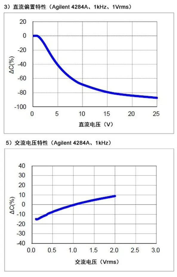
Test signal: For example, the following figure is taken from the CL31A106KAHNNNE characteristic table, showing the impact of DC bias and AC test signal amplitude on the observed capacitance value. In this case, slightly changing the amplitude of the AC test signal can cause the observed capacitance value to fluctuate between -15% and+10%. The impact caused by DC bias is greater; At only a quarter of the rated voltage, the capacitance of the device will be reduced by half. For those who believe that all deviations will not exceed the nominal tolerance of+/-10%, this may surprise them.

Please note that this degree of variation is common, and there is no significant difference in quality between the parts shown and similar products in this regard. However, the manufacturer of this product is very considerate in presenting the characteristics of a specific device clearly and clearly in the form of a characteristic table.
Temperature: The following figure shows several examples of capacitance series with different temperature characteristics changing with temperature. Except for Class 1 dielectric (C0G) devices, the minimum expected change in operating temperature for applications with significant changes is approximately 10%. Please note that the figure only illustrates the influence of temperature: other factors will further increase the magnitude of the observed capacitance value. Similarly, for those who believe that the prescribed ‘tolerance‘ is an overall concept, this may also be an unwelcome unexpected reality.
Time: Finally, ceramic capacitors (excluding Class 1 dielectrics) will experience aging, meaning that their capacitance will gradually decrease over time, starting from the last heating to the specific temperature of the material. This heating usually occurs during the initial manufacturing stage, but can also occur during the assembly stage. The degree of this impact depends on the material and is constantly accumulating, usually up to a few percentage points per tenfold. This post provides a more detailed description of this impact. The time factor can increase or mask the influence of other factors on the observed capacitance value (depending on the specific situation). Anyway, when ‘tolerance‘ is misunderstood as a total range, it can itself lead to the device exhibiting situations beyond the tolerance range.
In summary:
·The ‘tolerance‘ only represents one factor that affects the observed values of ceramic capacitors, rather than the sum of all factors.
·The impact of these other factors may be much greater than the specified tolerance value. But this cannot be considered as a product defect or non-compliance with product specifications.
·The test signal used, equipment temperature, and the time after the last aging of the equipment can all affect the observed capacitance of the ceramic capacitor. All these factors must meet the manufacturer‘s testing conditions in order to conduct effective capacitance measurements and ultimately determine whether the capacitor meets the manufacturer‘s specifications.
·The capacitance measurement function on many multimeters cannot effectively determine whether the product meets the manufacturer‘s specifications.
·If you need a known stable capacitor, there is no need to consider ceramic capacitors based on Class 1 dielectrics (C0G or NP0 being the most common).
|
Disclaimer: This article is transferred from other platforms and does not represent the views and positions of this site. If there is any infringement or objection, please contact us to delete it. thank you! |


