The Application of Constant Current Circuit in Power Supply
Time:2023-09-17
Views:685
Due to market demand, power modules are increasingly pursuing wide voltage inputs, which can cause the supply current to vary with the input voltage. In order to obtain a constant supply current for both high and low voltage inputs, a constant current circuit is added at the input end to achieve consistent performance.
Ideal constant current source
An ideal constant current source is one where the current does not change with the input voltage, is not affected by environmental temperature, and has an infinite internal resistance. However, there is still a gap between the actual constant current circuit and the ideal one, so it is necessary to select a suitable constant current source circuit based on the actual application.
Introduction to Several Simple Constant Current Sources
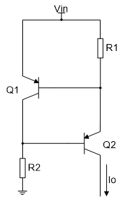
A constant current source circuit composed of two transistors, as shown in circuit diagram 1

Figure 1
A relatively constant current source is composed of two transistors of the same model, based on the relatively stable voltage of the transistor Vbe and the relatively small base current of the transistor compared to the collector current. The current Io=Vbe/R1; This constant current source does not use special devices, consisting of two transistors and two resistors, with low cost and adjustable current Io; The disadvantage is that the size of Vbe varies with changes in current and temperature. Vbe is large when the current is high, and Vbe is large when the temperature is low, so it is not suitable for use in places with high accuracy requirements.
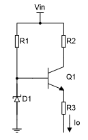
A constant current source circuit composed of a voltage regulator, as shown in circuit diagram 2

Figure 2
This constant current circuit mainly utilizes the stable voltage characteristics of the voltage regulator diode and the stability of the transistor Vbe to form a constant current circuit, Io=(Vd Vbe)/R3; The advantages of this circuit are low cost, adjustable current, and the disadvantages are poor temperature characteristics and low current stabilization accuracy, making it suitable for situations with low accuracy requirements.
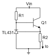
A constant current source composed of TL431, as shown in circuit diagram 3

Figure 3
TL431 provides a reference voltage Vref to form a constant current source, with a current Io=Vref/R2.
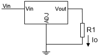
A constant current source composed of a three terminal voltage regulator, as shown in circuit diagram 4

Figure 4
The three terminal voltage regulator provides a constant voltage Vout, forming a constant current source, Io=Vout/R1.
The above are some common and simple constant current sources, and they have one common feature: low voltage regulation accuracy and low current Io. In addition to the few listed above, there are other similar constant current sources, but they are all based on a constant voltage source and will not be listed here.
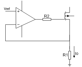
In the application process, if a high-precision and high current constant current source is needed, an operational amplifier can be used to form a high-precision and high current constant current source, as shown in circuit diagram 5

Figure 5
Using a constant current source composed of operational amplifiers, Io=Vref/R1.
Application of Constant Current Source in Wide Voltage Input Module
In modular power supplies, the short-circuit protection of low-power power supplies is generally not connected to external short-circuit protection circuits. The characteristics of this type of module are small power, small size, and low cost; Suitable for the current fiercely competitive market; However, they themselves have a fatal characteristic: there is a contradiction between the short-circuit protection function and the starting ability. If the starting ability is strong, the short-circuit protection will deteriorate; The stronger the short-circuit protection, the weaker the starting ability. Especially when an ultra wide voltage range input is required, the starting ability and short-circuit ability are less compatible.
For example, E4805UHBD-15W, a module power supply with 18-72VDC input and 15W output, if an RC starting circuit is composed of a resistor and a capacitor as shown in Figure 6, the current will vary with the input voltage. When there is a short circuit between low and high voltage, the burping cycle will vary greatly, and the short circuit power will be larger when there is a high input voltage; After adjusting the low voltage starting and short circuit protection, the high voltage short circuit protection will deteriorate, and the starting ability will be super strong. Conversely, adjusting the high voltage starting and short circuit capabilities will result in good low voltage short circuit protection, but poor starting ability can lead to poor starting.

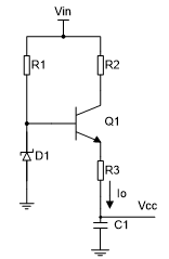
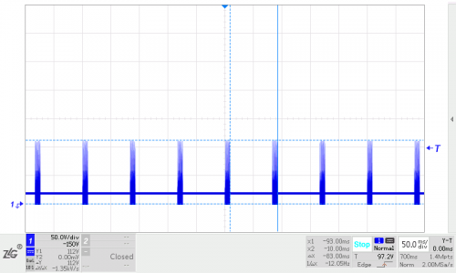
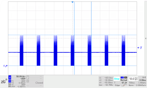

Figure 6
In order to solve the above contradiction, the starting circuit is replaced by a constant current circuit, as shown in Figure 7. The input current basically does not change with the change of input voltage. The two starting circuits provide the same starting current at low voltage. When the high voltage is short circuited, the short circuit power consumption of the second starting circuit will be much smaller, and the short circuit cycles of low voltage and high voltage will also be closer.

Figure 7
As shown in Figures 8 and 9, a constant current circuit was used to test the short-circuit waveform, and the contradiction between starting and short-circuit was solved by replacing resistor starting with a constant current circuit.

Figure 8

Figure 9
|
Disclaimer: This article is transferred from other platforms and does not represent the views and positions of this site. If there is any infringement or objection, please contact us to delete it. thank you! |


