Summary of a hodgepodge of self-excited oscillations in operational amplifiers
Time:2023-09-11
Views:704
I have read a lot of information on self-excited oscillations in operational amplifiers, and have also checked relevant resources online. I have obtained some summaries as follows:

1. Two conditions for operational amplifier oscillation
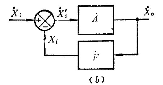
1. Loop gain greater than 1 (| AF |>1)
2. The phase difference of the signal before and after feedback is above 360 degrees, and the additional phase is above 180 degrees (due to the negative feedback being connected to the reverse end).

A (open loop gain)=Xo/Xi
F (feedback coefficient)=Xf/Xo
2. Operational amplifier oscillation judgment method:
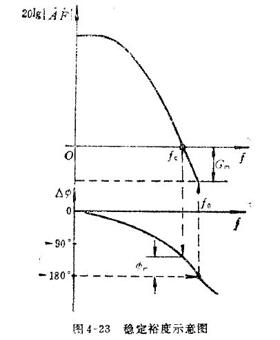
The commonly used method is phase margin, which means whether the phase offset exceeds 180 when 20lg | AF |=0

3. Methods for eliminating self-excitation:
According to the conditions of self-excited oscillations, eliminating oscillations can be achieved from two aspects:
(1) Reduce loop gain (but this method increases operational amplifier gain error)
For operational amplifiers, it means reducing the feedback coefficient F, in other words, the larger F, the greater the likelihood of self excited oscillations. For a resistance feedback network, the maximum value of F is 1, and a typical circuit with F=1 is a voltage following circuit. This is the reason why voltage following operational amplifiers are prone to oscillations (which is also why we often see operational amplifier manuals labeled with unit gain stability instructions, but the gain error of voltage following is relatively small).
For voltage feedback, the driving capacity of capacitive loads increases proportionally with the closed-loop gain. So, if the closed-loop gain is 1, VFA can stably drive a 100pF capacitive load, then when the closed-loop gain is 10, it can drive a 1000pF capacitive load
However, due to design reasons, the size of the closed-loop gain is usually not easily changeable, so the applicability of this method is not strong.
(2) Increase phase margin
Phase compensation:
According to the compensation principle, it is divided into lag compensation, lead compensation, and lag lead compensation
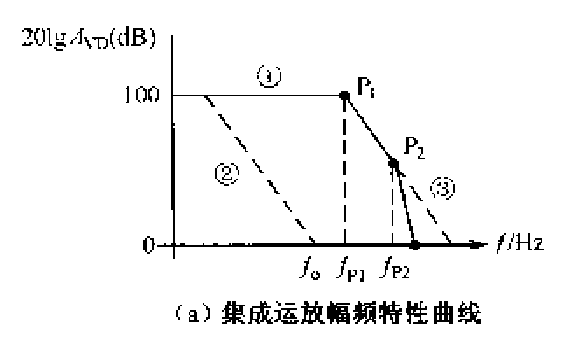
Lag compensation: Any compensation that causes the phase shift to lag is called lag compensation. Hysteresis compensation reduces the frequency of the main pole, which narrows the frequency band of the amplifier. (Similar to RC low-pass filtering) Curve ②
Advance compensation: Any compensation that causes the phase shift to advance is called advance compensation. Advance compensation causes a zero point in the amplitude frequency characteristic curve, which means the amplifier frequency band becomes wider (similar to RC high pass filtering) - curve ③

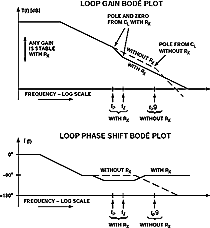
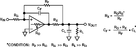
For the capacitance (CL) of the load, the loop gain is reduced by the output resistance and CL. Meanwhile, there is no longer a proportional relationship between phase and gain, and phase lag becomes the determining factor.
1. Out of loop compensation - lead compensation (suitable for small capacitive loads<1500pf or with a certain load impedance)
A resistor RX is connected in series between the output terminal of the operational amplifier and the load capacitor, typically with a resistance value of 10-100 ohms.


2. In loop compensation - lead compensation (suitable for large capacitive loads>1500pf or with variable load impedance)
Rx is located within the feedback loop of the operational amplifier, and a feedback capacitor is parallel connected to the feedback resistor (which can eliminate the input capacitance and stray capacitance of the operational amplifier to form poles). Generally speaking, Rx=50-200 Ω, and Cf is about 3-10pF

|
Disclaimer: This article is transferred from other platforms and does not represent the views and positions of this site. If there is any infringement or objection, please contact us to delete it. thank you! |


