BLDC Motor Control Design
Time:2023-08-18
Views:750
DC motors are widely used in the fields of servo automation and robotics. The working principle of an electric motor is based on the interaction between two mutually attractive and repulsive magnetic fields.
The two basic parts of a DC motor are the rotor (rotating) and the stator (fixed). The stator is a magnetic field sensor, while the rotor is a component affected by the magnetic field, represented by a circuit called an armature. There is a thin layer of air between these two components, called the "air gap".
The stator must generate a magnetic field as uniform as possible. The rotor is made of sheet iron and consists of movable pieces separated by insulators to increase resistance and reduce parasitic currents caused by magnetization.
Two common types of DC motors are called brushless motors and brushless motors (BLDC). BLDC represents a brushless permanent magnet motor. Unlike a brushless DC motor, it does not require any electrical contacts to slide on the motor shaft to operate.
In a brushless motor, the mechanical contact between the brush and the electrical contacts on the rotor closes the circuit between the power supply and the rotor winding. The rotor and brush generate a constantly changing direction of current, thereby reversing the magnetic field.
In brushless motors, current reversal is obtained electronically through a set of power transistors (usually IGBTs) controlled by a microcontroller. The main problem driving them is to understand the accurate position of the motor; Only in this way can the controller determine which phase to drive. The position of the rotor is usually obtained using Hall effect sensors or optical sensors. In terms of efficiency, due to reduced friction, brushless motors generate much less heat than equivalent AC motors.
In addition, the windings on the stator of a brushless motor have good heat dissipation ability, which can build a "smooth" motor without heat dissipation fins. When the motor operates in an environment filled with volatile compounds (such as fuel), it is crucial to have no sparks. In this type of motor, the magnet is located on the rotor and made of special materials, with very low inertia. This ensures extremely high speed and torque accuracy, as well as fast and efficient acceleration and deceleration.
Compared with traditional motors, BLDC motors have many advantages. Typically, their efficiency is improved by 15% to 20%, as they are brushless and require less maintenance, providing a flat torque curve at all rated speeds.
The development of semiconductor technology, the improvement of permanent magnets, and the growing demand for higher efficiency have led to the use of BLDC instead of brush motors in many applications. BLDC motors have entered many industries, including home appliances, automobiles, aerospace, consumer goods, healthcare, industrial automation equipment, and instrumentation (Figure 1).
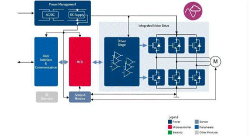
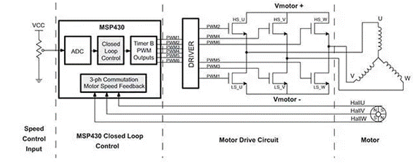
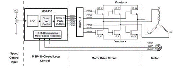

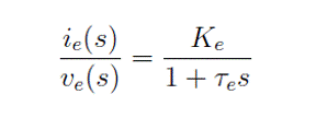

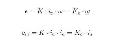


Figure 1: Example application of brushless DC motor control and driver (Image: Infineon Technologies)
BLDC motors can be configured in single-phase, two-phase, and three-phase configurations; The common one is three-phase. The number of phases corresponds to the number of windings on the stator, while the rotor poles can be any logarithm, depending on the application (Figure 2).
The rotor speed is directly proportional to the pulse width modulation (PWM) operating frequency of the motor, which is the basic operating frequency for controlling starting current, torque, and power.

Figure 2: A typical closed-loop control system for a three-phase BLDC motor includes a controller, driver, and power transistor half bridge H. (Image: Texas Instruments)
Equivalent Circuit of DC Motor
The research on DC motors and their control involves analyzing equivalent models to determine operating characteristics. Starting from studying the mathematical model of a DC motor, a driver can be selected to control the load.
The following equation represents the mathematical model of the rotor under simplified assumptions. Assuming the magnetic circuit is linear, mechanical friction is a linear function of motor speed (Figure 3).

Figure 3: Equivalent Wiring Diagram of DC Motor
In a DC motor, magnetic flux is generated by the windings on the stator. Assuming that the stator has only one polarity terminal, its characteristics are the inductance Le related to its winding and the resistor Re related to conductor leakage. The equation model of this circuit is:

By transforming variables in the Laplace domain:

Where Ke=1/R e is the stator gain, τ E=Le/R e is the stator time constant.
Similarly, assuming that the rotor has only one polarity terminal, its characteristics are the armature resistance R a (a few ohms) and the armature inductance L a. In addition, the influence of back electromotive force e (t) must be considered in the electrical model of the rotor, which corresponds to the voltage difference induced by the stator and is proportional to the rotational speed. The equation for the relevant circuit in Figure 1 is as follows:

Where v a (t) and i a (t) are the armature current and voltage, respectively.
Similarly, we will define the rotor gain (Ka) and rotor time constant( τ a) . The back electromotive force (e) and the mechanical torque transmitted by the motor, cm, can be defined as:

Ke and Kc are the two constants of the motor, called the elliptical constant and the torque constant, ω It‘s angular velocity.
The behavior of mechanical loads is almost always nonlinear. The linear model of the load can be obtained by equating the motor torque cm to the sum of three parameters: the load torque applied to the motor shaft, the parameter proportional to the motor rotation speed based on the friction coefficient F, and the parameter proportional to the derivative of the motor speed to the moment of inertia J; That‘s:

By performing the Laplace transform, we can define two terms: K m, mechanical gain, and e m, mechanical time constant, and obtain the following equation:

It expresses the direct relationship between position and armature current.
DC motor driver
The driver is the basic component of BLDC control. It is a power amplifier that generates voltage output to drive the high current high side and low side IGBT gates of the H-bridge circuit. The high side means that the source (in the case of MOSFETs) or emitter (in IGBT boxes) can fluctuate between ground voltage and higher motor voltage. The low side indicates that the source or emitter is always grounded.
ROHM Semiconductor‘s BM60212FV-CE2 integrated gate driver and other solutions are very suitable for driving a pair of high side and low side IGBTs. This device is compatible with 3.3V or 5V controller logic signals and provides a variable high side power supply voltage of up to 1200V and a gate control voltage of 24V simultaneously. Further enhancements include protection circuits, mainly under voltage blocking (UVLO) and desaturation protection (DESAT). The UVLO circuit can prevent overheating and damage during power on.
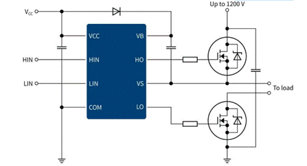

Figure 4: Typical High and Low Side Driver Connection Diagram (Image Source: Infineon Technologies)
Another example is Infineon‘s TLE987x series, which is suitable for a wide range of BLDC applications. It provides unparalleled integration and system costs to optimize target application areas. The TLE9873QXW40 device integrates the industry standard Arm Cortex-M3 core, enabling advanced engine control algorithms. Its peripherals include a current sensor, a subsequent approximate ADC synchronized with the acquisition and comparison unit used for PWM control, and a 16 bit timer (Figure 4).
STMicroElectronics‘ STSPIN motor driver for three-phase BLDC includes a power driver with a three-phase bridge configuration and a solution with integrated decoding logic for Hall effect sensors.
Toshiba has developed Intelligent Phase Control (InPAC) technology, which can monitor the current phase (current information) and voltage phase (Hall effect signal), and provide feedback to the motor current control signal to automatically adjust the phase control to ensure high efficiency. In fact, the phase of the Hall signal is automatically adjusted to match the phase of the motor driving current. High efficiency is independent of the speed, load torque, and power supply voltage of the motor.
The heat dissipation of BLDC motors is crucial, and their thermal management must ensure high efficiency. Losses can be classified based on the resistance and parasitic capacitance of the device.
During the switching period, the power consumption of the transistor is proportional to the power supply voltage, gate charge (QG), and switching frequency. If you do not want to affect efficiency at a given power supply voltage, you must offset the increase in switching frequency to increase power density by reducing QG.
The Allegro MicroSystems A89331 sensorless driver is designed to improve thermal efficiency, reduce power consumption, and reduce data center costs. The new power outage braking (PLB) function also improves safety and reduces material requirements. The unique PLB function built-in in A89331 can brake fans that cannot function properly, thereby eliminating additional power consumption and improving thermal efficiency.
Without electronic hardware control, the mechanical structure of the engine cannot complete its work. Energy efficiency, torque, and sensing are the main characteristics to keep in mind when selecting drivers and application types. The internal operation of the motor, coupled with mathematical models, allows us to easily evaluate the operating characteristics and then evaluate the selection of the driver.
|
Disclaimer: This article is transferred from other platforms and does not represent the views and positions of this site. If there is any infringement or objection, please contact us to delete it. thank you! |


