Here are a few simple and low-cost methods to suppress complex FM frequency band conducted radiation
Time:2023-07-14
Views:849
Although EMI shielding and ferrite clamps are popular EMI solutions, they are expensive, bulky, and sometimes ineffective in use. We can reduce these noises by understanding the sources of EMI noise in the FM frequency band and utilizing circuit and PCB design techniques to suppress them from the source.
The EMI performance of the power network is critical in noise sensitive systems, such as automotive circuits, especially when Switched-mode power supply is involved. Engineers may need to spend a lot of time reducing conducted radiation (CE) and electromagnetic radiation disturbance (RE). Especially when measuring CE, the FM frequency band (76 MHz to~108 MHz) may be the most difficult area to meet the requirements and pass the test. Designers may need to spend a lot of time solving this problem. Why is CE noise in the FM frequency band so difficult to eliminate?
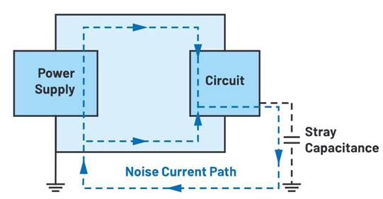
The noise in low frequency (AM band) CE is mainly differential mode (DM) noise. The noise in high-frequency (FM frequency band) CE is mainly common mode (CM) noise. The common mode noise current is generated by nodes with voltage changes on the PCB. The current leaks through the stray capacitor to the reference ground and then returns to the positive and negative input cables (see Figure 1). Due to the complexity of the stray capacitance around the PCB, it is not possible to simulate the stray capacitance and estimate the conducted EMI in the FM frequency band. It is best to test the circuit board in the EMI room.

Figure 1. Conducted radiation, common mode noise current path.
In the laboratory, some effective methods can effectively reduce EMI in the FM frequency band, including changing switch frequency, switch voltage swing rate, switch node layout, thermal circuit layout, inductance, and even the position of input cables and loads. The effectiveness of each method varies depending on the circuit board.
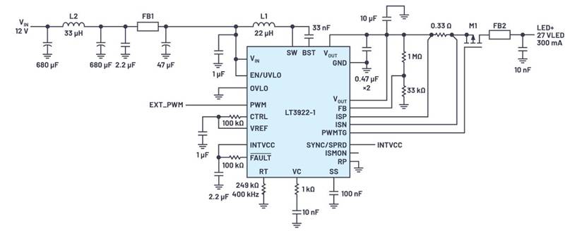
This article explores several simple low-cost methods that can reduce the FM frequency band conducted EMI on circuit boards without the use of ferrite clamps or shielding. We loaded the LT3922-1 automotive HUD LED driver onto the circuit board in a certified EMI room, and then performed current probe CE testing to verify the results, as shown in Figure 2.

Figure 2. Simplified schematic diagram of LT3922-1 automotive HUD LED driver.
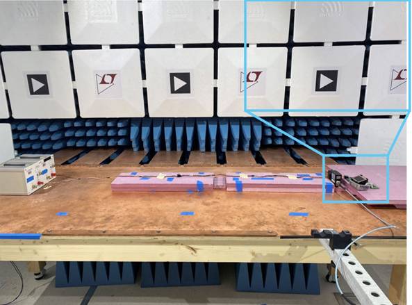
In this test, we used the current probe method to measure CE based on the CISPR 25 EMI setting, as shown in Figure 3. We can use voltage probe method or current probe method to test CE, but it is generally believed that the current probe method has stricter standards. The current CE method is not used to measure the voltage output of LISN, but instead uses a high bandwidth current probe to measure the CM noise signal transmitted through power lines or wiring harnesses, which are 50 mm and 750 mm away from the DUT, respectively. Collect peak and average data of CE during each scan and compare with published standard limits.

Figure 3. CISPR 25 Current Probe Conducted Radiation (CE) Settings in EMI Test Room (50 mm)
When using the current probe method, the average CE limit in the FM frequency band described in CISPR 25 Class 5 is as low as -16 dB µ A. Here, we present several methods that can effectively improve the test results in the FM frequency band when using the current probe method to test CE. Many of these methods can also be used to improve test results when using the voltage probe method to test CE.
Unless otherwise specified, all tests conducted in this study enabled SSFM function. After enabling SSFM, the EMI peak at both the switching frequency and its harmonics will decrease.
Common mode choke can suppress EMI noise in the EM frequency band
CM noise current is generated during the switching process, leaks to the reference ground through stray capacitors, and then returns through the input power supply and circuit in the same direction. By using a CM choke to increase the common mode impedance in the circuit, excess CM noise can be suppressed.
Figure 4 shows the CE results of the 50 mm and 750 mm average current probes, comparing the initial circuit without the choke and the circuit with the choke installed before the LED driver circuit. The figure also shows environmental background noise as a reference. The FM frequency band CE (76 MHz to~108 MHz) has decreased by more than 8 dB µ A.

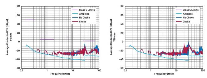
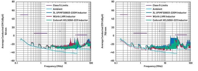
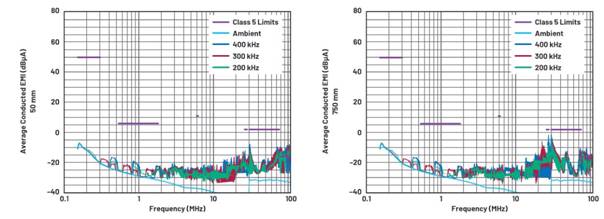

Table 1. Comparison of Technical Specifications of Inductors Used in Testing
Inductance brings changes
The rapidly changing voltage and current act on the main inductor, making it an electromagnetic antenna. Therefore, the inductor can become a source of CE noise in the FM frequency band. We can use various inductance methods to improve EMI test results. For example, the direction of inductor installation can bring about changes. The radiation of shielded inductors is usually lower than that of unshielded inductors, and some magnetic core materials have a stronger inhibitory effect on H and E field radiation than other materials. For example, when the inductance of iron powder and metal alloy powder exceeds 1 MHz, the shielding effect of the E-field weakens. MnZn and NiZn perform better at higher switching frequencies. The inductance performance with exposed solder pads is not as good as that without exposed solder pads. Connecting the long lead of the internal coil to the high dV ⁄ dt (switch) node will significantly increase the E field radiation.

Figure 4. Current probe CE test shows that the radiation in the FM frequency band is lower when using a common mode choke

Figure 5. Comparison of Current Probe CE Test Results (Inductance)

Figure 6. Comparison of Current Probe CE Test Results (Switching Frequency)
Three 22 µ H shielded inductors were used for testing, as shown in Table 1. Evaluate EMI in the same circuit without using CM chokes, with each inductor installed in the direction that provides the best performance. The comparison results are shown in Figure 5. In this study, the Coilcraft XEL inductor had the best noise suppression performance in the FM frequency band, reducing EMI in the FM frequency band by 5.1 dB compared to other 3L inductors.
The lower the switching frequency (fsw), the smaller the noise in the FM frequency band
Reducing the switching frequency can reduce the emission energy at a given high frequency. In Figure 6, a current probe CE test was performed on the circuit without the use of a CM choke, and the test results were compared at switching frequencies of 200 kHz, 300 kHz, and 400 kHz. All components except RT remain unchanged. The test results show that the EMI in the FM frequency band is the lowest at 200 kHz, and the radiation is reduced by 3.2 dB compared to 400 kHz.
Reduce antenna noise by reducing the area of switch nodes
A high dV ⁄ dt switching node is a noise source that generates capacitive coupling, increasing CM EMI noise in CE. It also works like an antenna, radiating electromagnetic noise into space and also affecting radiated EMI. Therefore, minimizing the switch node area on PCB layout can improve EMI performance. To test this on the PCB circuit board, we removed some of the copper cores and moved the inductor closer to the IC (as shown in Figure 7) to reduce the switch node area. We tested the EMI before and after cutting the copper core, and the test results are shown in Figure 8.
The results showed that the 50 mm current probe CE test reduced by 1 dB at 105 MHz, while the 750 mm test showed no significant improvement. This result indicates that the copper core area is not the main factor affecting EMI in the FM frequency band in this application. Nevertheless, it is still worth trying to minimize the switch node area in order to achieve a low EMI PCB layout or during efforts to eliminate EMI.
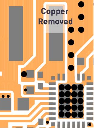
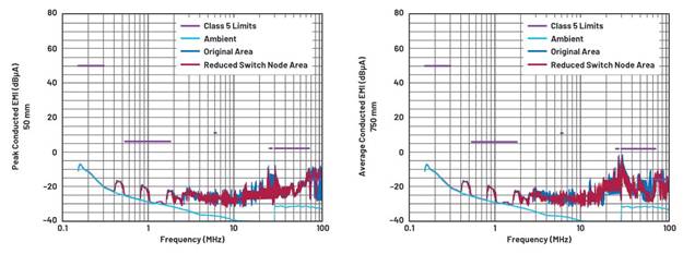

Figure 7. Switching node cutting area

Figure 8. Comparison of Current Probe CE Test Results (Switch Node Area)
conclusion
The EMI performance of power supplies mainly depends on the performance of power supply ICs, but even high-performance ICs can only achieve low EMI by selecting appropriate components and effective PCB layout. In this article, we utilized a circuit board based on LT3922-1 automotive HUD LED driver to explore several methods for suppressing invasive radiation (CE) in the FM frequency band.
Installing a CM choke on the positive and negative input cables will increase the impedance in the common mode noise current loop. The EMI performance results of different inductors with different core materials, core structures, and coil structures also vary. It is difficult to determine which inductor has the best performance solely by looking at technical specifications, but it can be compared in EMI laboratories.
The installation direction of the inductance on the PCB is also important. Reducing the switching frequency and reducing the copper area of the switching nodes can help reduce CE within the FM frequency band. If the DUT is a switch regulator circuit using a controller (external MOSFET), it can further reduce the FM frequency band EMI by reducing the switch voltage swing rate and minimizing the thermal loop area as much as possible.
|
Disclaimer: This article is transferred from other platforms and does not represent the views and positions of this site. If there is any infringement or objection, please contact us to delete it. thank you! |


