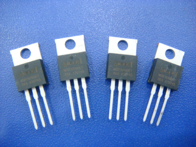
Key points of Schottky diode application
Time:2023-07-11
Views:848
Schottky diodes are widely used in switching power supplies. Everyone in the electronics industry has heard of Schottky, but do we truly understand the internal structure, application range, and why Schottky is widely used in high-frequency switching power supplies? So let‘s walk into Schottky‘s world together and find the answer we want.


There are various types of diodes: germanium diodes, silicon diodes, gallium arsenide diodes, etc; According to the structure of the tube core, it can be divided into surface contact diodes and point contact diodes; According to different purposes, it can be divided into rectifier diodes, detector diodes, voltage regulator diodes, variable capacitance diodes, photodiodes, light emitting diodes, switching diodes, fast recovery diodes, etc; According to the type of junction, it can be divided into semiconductor junction diodes and metal semiconductor junction diodes. However, Schottky diodes belong to metal semiconductor junction diodes.

1、 The Internal Structure of Schottky Diodes
Schottky diode, also known as Schottky barrier diode (SBD for short), is a diode made based on the barrier layer formed by contact between metal and semiconductor, as shown in Figure 1. Its main characteristics are small forward conduction voltage drop (about 0.45V), short reverse recovery time and low switching loss. It is a low-power, ultra-high speed semiconductor device. Schottky diodes differ greatly from PN junction diodes in terms of structural principles. Their interior is composed of anode metal (barrier layer made of materials such as molybdenum or aluminum), silicon dioxide (SiO2) electric field elimination material, N-epitaxial layer (arsenic material), N-type silicon substrate, N+cathode layer, and cathode metal, as shown in Figure 1. A Schottky barrier is formed between the N-type substrate and the anode metal. When positive bias is applied at both ends of the Schottky barrier (anode metal is connected to the positive pole of the power supply, and N-type substrate is connected to the negative pole of the power supply), the Schottky barrier layer becomes narrower and its internal resistance becomes smaller; On the contrary, if reverse bias is applied at both ends of the Schottky barrier, the Schottky barrier layer becomes wider and its internal resistance becomes larger.

Figure 1
The problem with Schottky diodes is that they have low withstand voltage and high reverse leakage current. The general level of Schottky diodes currently used in power conversion circuits is withstand voltage below 150V, average current below 100A, and reverse recovery time between 10 and 40ns. Schottky diodes are ideal for high frequency and low voltage circuits.
2、 Schottky diode applications
In switching power supplies, we often use Schottky diodes, but due to different manufacturers and other reasons, the performance varies greatly. When choosing Schottky diodes, we must consider the following parameters:
2.1. Conduction voltage drop VF
VF refers to the voltage drop at both ends of the diode when it conducts forward. The greater the current passing through the diode, the greater the VF; The higher the diode temperature, the smaller the VF.
2.2. Reverse saturated leakage current IR
IR refers to the current flowing through the diode when a reverse voltage is applied at both ends of the diode. The Schottky diode has a higher reverse leakage current, so choosing a Schottky diode is to try to choose a diode with a smaller IR.
2.3. Rated current IF
The average current value calculated based on the allowable temperature rise during long-term operation of a diode.
2.4. Maximum surge current IFSM
Excessive forward current allowed to flow. It is not a normal current, but an instantaneous current, which is quite large.
2.5. Maximum reverse peak voltage VRM
Even if there is no reverse current, as long as the reverse voltage is continuously increased, sooner or later the diode will be damaged. The reverse voltage that can be applied is not an instantaneous voltage, but a repeatedly applied forward and reverse voltage. Due to the AC voltage applied to the rectifier, its maximum value is a specified important factor. The maximum reverse peak voltage VRM refers to the maximum reverse voltage that can be applied to avoid breakdown. At present, the highest VRM value for Schottky is 150V.
2.6. Maximum DC reverse voltage VR
The maximum reverse peak voltage mentioned above is the peak voltage repeatedly applied, and VR is the value obtained by continuously applying DC voltage. For DC circuits, the maximum DC reverse voltage is important for determining allowable and upper limits
2.7. Maximum operating frequency fM
Due to the presence of junction capacitance in PN junctions, their unidirectional conductivity will deteriorate when the operating frequency exceeds a certain value. The fM value of Schottky diodes is high, with a maximum of 100GHz.
2.8. Reverse recovery time Trr
When the working voltage changes from forward voltage to reverse voltage, the ideal situation for diode operation is that the current can be instantly cut off. In fact, it usually takes a little time to delay. The amount that determines the current cutoff delay is the reverse recovery time. Although it directly affects the switching speed of the diode, it does not necessarily mean that a small value is good. That is, when the diode suddenly reverses from conduction, the reverse current decays from a large amount to the time required to approach IR. This indicator is crucial when high-power switching tubes operate in high-frequency switching states.
2.9. Maximum dissipation power P
When a current flows through a diode, it absorbs heat and raises its own temperature. In practice, the external heat dissipation also has a significant impact on P. Specifically, it is the voltage applied to both ends of the diode multiplied by the current flowing through it and the reverse recovery loss.
3、 Comparison between Schottky and Fast Recovery Diodes
Fast recovery diodes are diodes with a short reverse recovery time (below 5us), and their forward voltage drop is higher than that of ordinary diodes (0.8-2V). The reverse voltage withstand is below 1200V, and their performance can be divided into fast recovery and ultra fast recovery, with the latter reaching below 100ns.
Schottky diodes have a reverse recovery time of less than 10ns, high reverse leakage current, low withstand voltage, and are generally used in low voltage applications below 150V.
The difference between Schottky diodes and fast recovery diodes is that the recovery time of the former is about 100 times smaller than that of the latter, while the reverse recovery time of the former is about a few nanoseconds. The former has the advantages of low power consumption, high current, and ultra high speed; The latter has a high switching speed and can also achieve high voltage resistance, with small reverse leakage, making it suitable for applications with high voltage and frequency.
In addition, the ESD withstand capacity of Schottky diodes is lower than that of fast recovery diodes.
|
Disclaimer: This article is transferred from other platforms and does not represent the views and positions of this site. If there is any infringement or objection, please contact us to delete it. thank you! |


