Use M5Stack core to control servo motor based on Potentiometer
Time:2023-06-17
Views:927
M5Stack is a modular, stackable, and programmable development module designed for quickly and easily building IoT projects and creating prototypes. This module is based on an ESP32 microcontroller and comes with various sensors, inputs, outputs, and a color liquid crystal display (LCD). In addition, the M5Stack core is packaged in rectangular modules, measuring 54 x 54 x 18 mm, and is equipped with a 2-inch Thin Film Transistor (TFT) LCD.
As mentioned earlier, the device has multiple input and output options, such as three buttons, a speaker, and a microSD card slot. Figure 1 illustrates the M5Stack kernel.

Figure 1. M5Stack. Image provided by M5Stack
One of the unique features of the M5Stack kernel is its modular design ecosystem. This module can be easily stacked with other M5Stack modules, allowing users to add additional features and expand the functionality of their projects. The M5Stack modular ecosystem provides various modules, such as camera, GPS, and battery module units.
In this article, we will explore angle sensors and servo motor units using the M5Stack core. The result of this hands-on project is to build a servo motor controller based on Potentiometer, with M5Stack TFT display.
Project Overview - Understanding Human Computer Interaction (HCI)
The servo motor controller project based on M5Stack Potentiometer will demonstrate the versatility and ease of use of off the shelf electronic products and software to build human-computer interaction (HCI) devices. The purpose of this project is to demonstrate how to use a small controller based on ESP32 to implement HCI concepts such as human-computer interaction. The platform based on ESP32 will have human-machine interaction with electromechanical objects. This project will enable readers to understand how to use M5Stack‘s TFT LCD to display and obtain interactive data from electromechanical systems. Such data can be used to explore the machine learning concept of network Physical system (CPS) using programming languages such as Python, PyTorch and Pandas.
As a key technology for this project, it is recommended to refer to the M5Stack electronic blue book. More specifically, Chapter 2 "M5Stack Unit Hands-on Practice" provides technical insights into the electronic circuits and settings of ESP32 modular controllers and programmable sensing and control units. This book also includes hands-on projects and interactive quizzes to attract readers. Basically, you can consider this project as an extension of this book; Therefore, this project will not explain detailed software setup instructions.
Set up M5Stack
The overall concept of this project is to demonstrate the prototype construction of a small servo motor controller using the M5Stack kernel as the main ESP32 embedded platform. The initial setting of the project is to add an external Potentiometer to control the servo motor. The Potentiometer will provide rotation information to the M5Stack core. Then, the M5Stack converts the analog voltage divider data into an equivalent pulse width modulation (PWM) control signal to operate the electrical wired servo motor. Figure 2 shows the system diagram of the prototype.
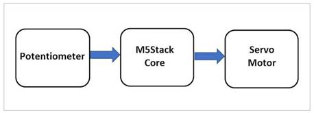
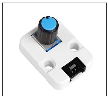

Figure 2. Block diagram of servo motor control system based on M5Stack Potentiometer.
Next, use the same internal electronic components as the angle sensor to connect the Potentiometer circuit to the ESP32 microcontroller of the M5Stack. The M5Stack angle sensor is composed of a 1 K Ω resistor connected in series with a 10 K Ω potentiometer. This circuit configuration provides a voltage divider function, allowing a series of discrete analog signal values to appear on the specified ESP32 Analog Digital General Input Output (GPIO) pin. Figure 3 shows the M5Stack angle sensor.

Figure 3 M5Stack angle sensor unit. Image provided by M5Stack
In addition, this circuit method allows the output voltage of the Potentiometer relative to the ground to be+3.3 V, and the GPIO pin of the ESP32 microcontroller meets the+3.3 V standard. Therefore, the output voltage of the voltage divider circuit+3.3V will not damage the ESP32 microcontroller. The electronic circuit schematic diagram of the self-made angle sensor is shown in Figure 4.
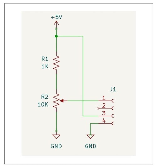

Figure 4. Electronic circuit schematic diagram of self-made angle sensor.
Please note that the J1 reference symbol represents the four pin female connector welded to the angle sensor PCB.
From here, you can use the electrical wiring diagram shown in Figure 5 as a reference to connect the self-made software angle sensor to the M5Stack, so as to connect the electronic circuit on the solderless Breadboard.
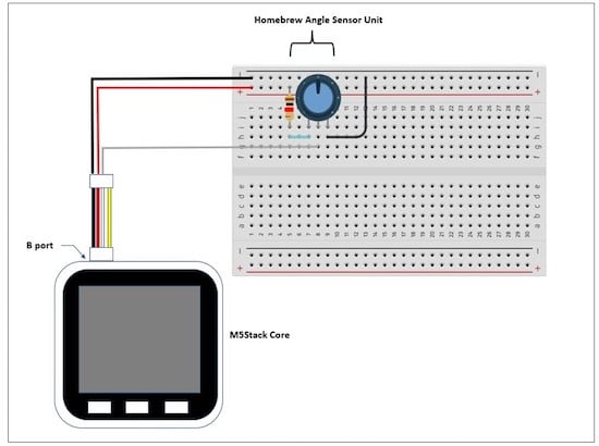

Figure 5. Self made angle sensor solderless Breadboard diagram.
Please remember that you can use UiFlow software to design the TFT LCD layout for M5Stack - we will introduce this in the next section.
Next, you will use DuPont wire to create an extension harness between the M5Stack and the home-made angle sensor solderless Breadboard circuit. As shown in Figure 5, insert three DuPont wires into the white four pin female connector to electrically connect the circuit to the M5Stack controller. Figure 6 illustrates the electrical wiring interface connection and connection method.
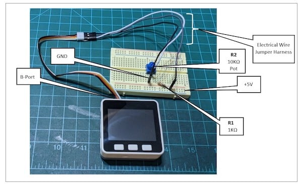
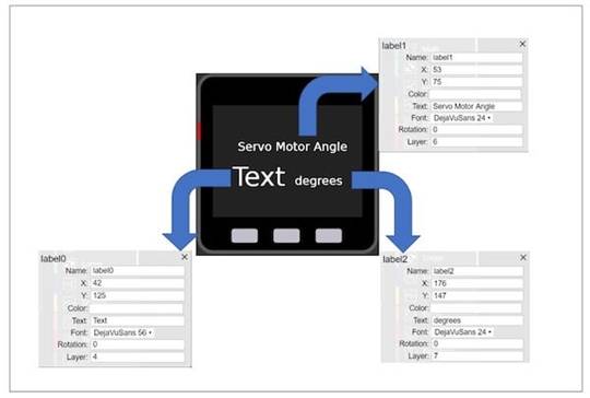

Figure 6. Solderless Breadboard wiring from Potentiometer to M5Stack core.
Introduction to UiFlow Software
For this project, I used a program called UiFlow. UiFlow is a software development platform aimed at simplifying the programming and prototyping process of M5Stack products for controllers, modules, sensors, and units. This software provides a graphical user interface (GUI) for programming the M5Stack ESP32 microcontroller. Developers can drag and drop code blocks and create logical code to program the ESP32 microcontroller. UiFlow allows encoding using online editors or desktop software packages.
The UiFlow online editor can be obtained from the M5Stack website at the following address. There are also desktop versions available for Windows, Apple, and Linux based computers.
The layout design of M5Stack core TFT LCD display Potentiometer rotation data is shown in Figure 7.

Figure 7. Configure M5Stack Core TFT LCD to display Potentiometer angle information.
To learn more about UiFlow, you can go to Chapter 2 of the M5Stack e-book to learn more.
Display Potentiometer reading
After connecting the Potentiometer to the M5Stack core, software is required to display the rotation value of electrical components. The UiFlow software will be used to display the rotation angle of the Potentiometer (in degrees), and the code block contains the three main operations of the servo motor controller.
The function of instruction code block includes:
• Read raw data from Potentiometer to variable
Provide appropriate variable scaling factors to ensure correct angle display
Display angles in degrees
The UiFlow code block is shown in Figure 8.
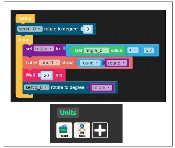
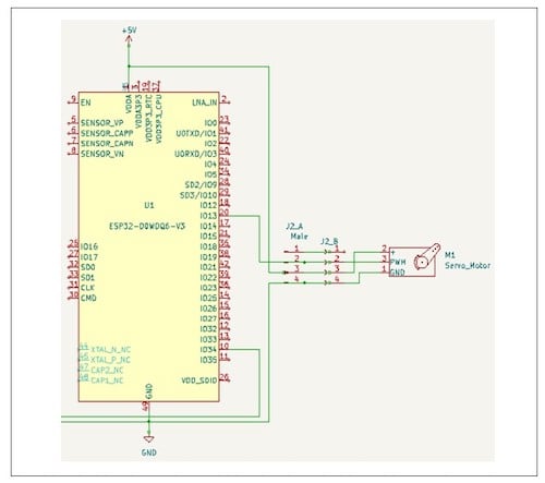
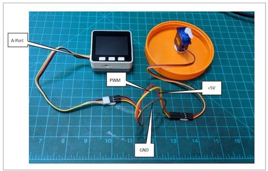
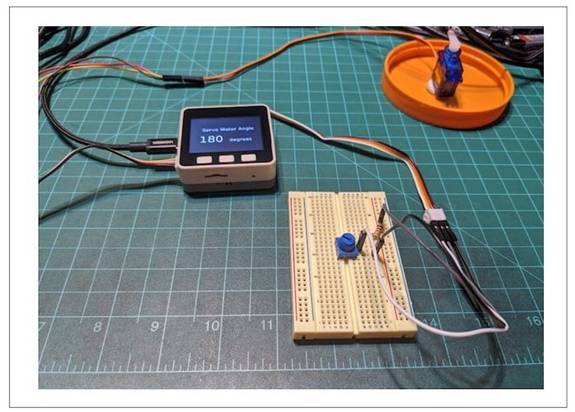

Figure 8 UiFlow Potentiometer angle display code block.
In addition to the code block, servo and angle sensor units are also included in the code block palette. These units will add a new set of code blocks to correctly operate these devices throughout the entire controller product prototype. As shown in Figure 8, "servo_0, servo_0 rotation angle" and "get angle_0 value" are new unit instructions added to the code block palette. You can include these code blocks by selecting the unit plus button. Selecting servo and angle units from the device list will add the required code blocks to the palette to complete the code construction of the project controller. By selecting the RUN button on the software IDE control panel, the UiFlow code block will be executed on the M5Stack.
Using UiFlow to Control Servo Motors
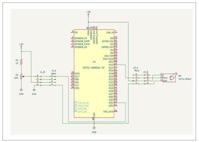
In addition to displaying the rotation angle of the Potentiometer, the UiFlow code block (as shown in Figure 8) also controls the servo motor. Connecting the servo motor to the M5Stack requires the same electrical wiring technology as the Potentiometer. The schematic diagram of some electronic circuits, as shown in Figure 9, illustrates the electrical wiring of the servo motor connected to the M5Stack ESP32 GPIO13 pin.

Figure 9. Partial electronic circuit schematic diagram: servo motor attached to the M5Stack ESP32 microcontroller.
J2 on the electronic circuit schematic diagram_ The A connector represents the A port on the M5Stack. J2_ The reference mark B represents the wire jumper harness pins inserted into the black three pin female connector of the servo motor.
The electrical wiring from the M5Stack Core to the servo motor is shown in Figure 10.

Figure 10 The servo motor is electrically connected to the M5Stack.
The completed prototype of servo motor controller based on M5Stack Potentiometer is shown in Figure 11.

Figure 11. Prototype construction of the final M5Stack servo motor controller based on Potentiometer.
As the final reference of the project, Figure 12 shows the complete electronic circuit schematic diagram of the servo motor controller based on M5Stack Potentiometer.
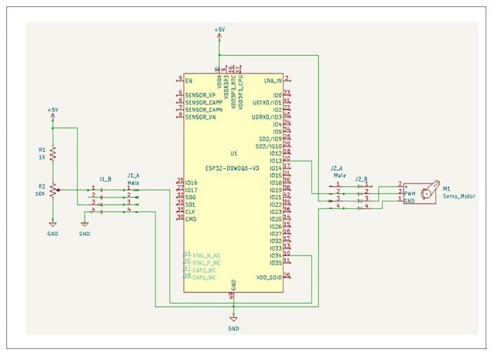

Figure 12. Schematic diagram of electronic circuit of servo motor controller based on M5Stack Potentiometer.
|
Disclaimer: This article is transferred from other platforms and does not represent the views and positions of this site. If there is any infringement or objection, please contact us to delete it. thank you! |


