TI utilizes two control schemes to reduce the noise of BLDC motor drivers
Time:2023-06-03
Views:1002
Brushless DC motors (BLDCs) have replaced AC induction motors and become increasingly common in general electrical applications such as fans, air purifiers, washing and drying machine pumps, and medical CPAP blowers.



However, the modulation of BLDC motors generates noise, which can lead to environmental background noise, especially in situations where open concept planar planning is very popular in office and home environments.
To help address these noise related issues, Texas Instruments (TI) today announced the launch of two new 70 W sensorless BLDC motor drivers, namely MCT8316A and MCF8316A. These drivers claim to be highly integrated codeless chipsets that use trapezoidal control and field oriented control (FOC), respectively.

Several examples of common noise levels in electrical appliances. Screenshot provided by Texas Instruments
The overall goals of these new chips are to reduce audible noise sources from daily applications, reduce the solution board size by up to 70%, and shorten the overall design time for BLDC tuning (possibly as short as 10 minutes)
Considering these goals, let‘s take a look at TI‘s products.
Overview of MCx8316A Chip
MCT8316A and MCF8316A operate with general electrical parameters, including a working range of 4.5 V to 35 V and a peak output of up to 8A. In addition, these chips are designed specifically for speed control motor applications that require 12 V to 24 V BLDC or permanent magnet synchronous motors.

Overview of MCx8316A chip. Screenshot provided by Texas Instruments
A decisive feature of the MCx8316A driver series is noise reduction. Specifically, MCT8316A supports 120 ° and 150 ° modulation, and can improve acoustic performance through trapezoidal control schemes.
Meanwhile, MCF8316A using FOC scheme utilizes automatic dead time compensation to reduce the harmonic content fed to the motor, thereby reducing noise within the audible range.
What is the difference between trapezoidal control and magnetic field oriented control in a family with two types of chips and two control schemes?
Trapezoidal Control and FOC in BLDC Motors
There are two general types of BLDC motors, including Hall effect sensor driven architecture and sensorless architecture. Although more complex, sensorless architecture is a more popular choice. For sensorless operation, two control schemes have emerged.

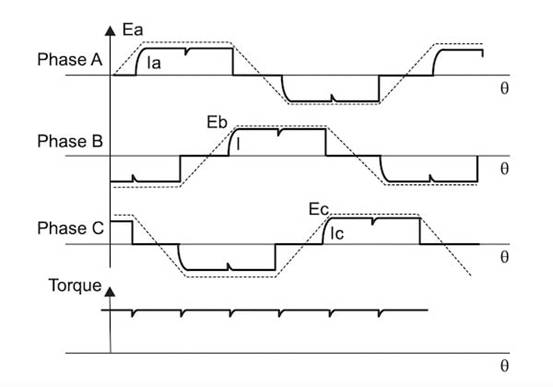
The timing diagram of the trapezoidal control scheme. Screenshot provided by Texas Instruments
The working principle of trapezoidal control is to assert two phases at any given time. Therefore, as shown above, no torque will be generated during zero crossing of any phase.
The effect of this scheme is to generate ripple at every 60 ° zero crossing phase, thereby generating harmonics. In 120 ° mode, the BLDC driver will use a high resistance state for the remaining 60 ° of each cycle.
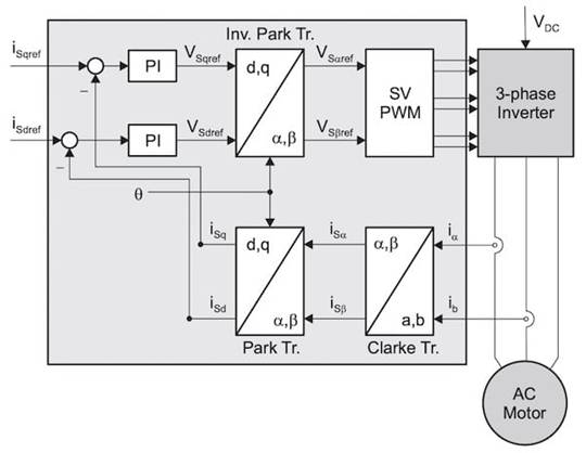
On the contrary, the magnetic field oriented control scheme requires significantly more complexity in the conversion of feedback control.
The output of the three-phase inverter generates a sinusoidal signal, which is sampled and fed through the Clarke transform and then Park transform.

Basic block diagram of magnetic field oriented control. Screenshot provided by Texas Instruments
The results of these two transformations realize direct torque control by converting the stator current vector from a three-phase time-varying system to a two coordinate time-invariant system.
How to Reduce Noise with MCx8316A Chip
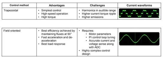
The two control schemes used to control BLDC motors each have their own advantages and disadvantages. Each method produces harmonic artifacts that contribute to acoustic noise.

The advantages and disadvantages of two sensorless BLDC control schemes. Screenshot provided by Texas Instruments
It is said that modulation and dead time compensation are crucial for reducing audible noise in motor motion. To be precise, MCF8316A uses a resonant controller to compensate for the dead time between the high and low side switch MOSFETs, in order to reduce the harmonic content to zero.

Enabling dead time compensation within MCF8316A can eliminate audible harmonics (left), resulting in a purer sine signal (right). Screenshot provided by Texas Instruments
The impact on the sinusoidal output and subsequent Fast Fourier Transform (FFT) is shown above.
Similarly, the FFT response of trapezoidal control schemes (such as MCT8316A) is improved by dynamically switching between 120 ° and 150 ° using the chip‘s variable commutation scheme, by "windowing" the amount of time the motor phase is in Hi-Z mode
In summary, this noise reduction solution seems promising for many applications, especially for consumer products.
|
Disclaimer: This article is transferred from other platforms and does not represent the views and positions of this site. If there is any infringement or objection, please contact us to delete it. thank you! |


