What are the precautions for the circuit of the audio amplifier
Time:2023-05-07
Views:1044
Power amplifiers are a crucial part of audio electronics. It is commonly used to amplify the power of input signals many times. In audio electronics, operational amplifiers increase the voltage of the signal, but cannot provide the current to drive the load. In this article, we will discuss how to create a 40W amplifier using TDA2040 power amplifier, 2 power transistors, and a 4 Ω impedance speaker.

The topology of the amplifier
In a chain system of amplifiers, the power amplifier is used for the final stage before the load. Generally speaking, the topology of an audio amplifier system is as follows.

As shown in the above figure, the power amplifier is the last stage connected to the load. In general, before the power amplifier, it is necessary to use a preamplifier and a voltage control amplifier to correct the signal. At the same time, in some cases, tone control is also required, and the circuit for tone control should be placed in front of the power amplifier.
Understand your load
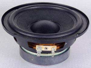
In audio amplifier systems, the load and the load driving capacity of the amplifier are important parameters that need to be considered. The main load of the power amplifier is the speaker. The output of the power amplifier depends on the impedance of the load, so an inappropriate load can affect the efficiency and stability of the power amplifier.

Speakers are both inductive and resistive loads. The power amplifier outputs AC power, so the impedance of the speaker is one of the key factors in power transmission.
In audio electronics, different speakers have different power and impedance. The majority of speakers on the market are 4 Ω, 8 Ω, 16 Ω, and 32 Ω, with 4 Ω and 8 Ω having lower costs. At the same time, we need to know that the amplifier labeled 5W, 6W, or 10W refers to RMS (effective value).
Construction of a simple 40W amplifier

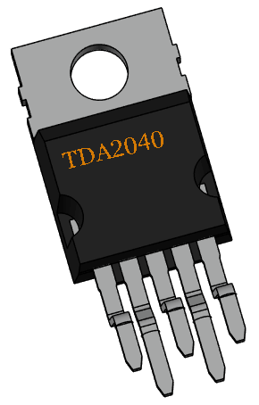
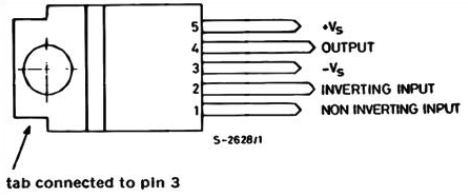
The above image shows TDA2040, which is a common audio amplifier. It is packaged as Pentawatt and has 5 pins. The pin diagram can be found in the specification book, as shown in the following figure.

1: In phase input terminal;
2: Inverted input terminal;
3: Negative power supply;
4: Output terminal;
5: Positive power supply.
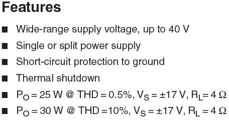
The top raised part is connected to pin 3, which is the negative power supply. If you want to add a heat sink, you should also use the same connection method. We can find from the specifications.

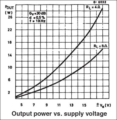
The above parameters demonstrate the good performance of the IC. It provides short circuit protection to ground. Similarly, thermal protection provides additional safety protection in the event of overload. From the last two pieces of data, we can see that TDA2040 can output 25W under a load of 4 Ω and ± 17V. In this case, THD (Total Harmonic Distortion) is 0.5%. Under the same configuration, to obtain a 30W output, the THD should be 10%.
The specification also provides a diagram of the relationship between power supply voltage and output power.

From the figure, it can be seen that if a power supply greater than ± 15V is used, we can achieve an output of over 26W.
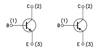
In order to generate additional voltage, we also need two power transistors NPN and PNP. Here, we use BD712 and BD711. Both transistors are packaged in TO-220C.
The pin diagrams of both are shown below.

In order to achieve perfect operation without affecting THD, we need a 36V input to achieve a 40W output. Although this circuit only needs 15V to 40V to start.
Required components
36V power output
4 Ω 40W speaker
1.5 Ω 0.5W resistor x 4
100 Ω 0.25W resistor x 4
12 Ω resistor x 1
1 Ω 2W resistor x 1
470nF capacitor
100uF capacitor
TDA2040
radiator
Diode 1N4148 x 2
220nF capacitor
2200uF capacitor
4.7uF capacitor
BD711 and BD712
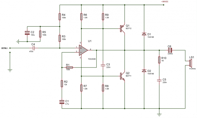
Circuit diagram and principle

The circuit diagram of a 40W audio amplifier is also relatively simple; After amplifying the signal, TDA2040 provides a RMS power of 25W. The remaining power amplification is achieved by BD711 and BD712 transistors. The input capacitor 470nF is a DC isolated capacitor that only allows AC signals to pass through. Another important factor is single power supply. Because the amplifier is powered by a single power source, the input signal needs to be raised by a few volts to enable the amplifier to amplify the signal at positive and negative peaks. Resistors R6, R9, R7, and R8 are responsible for providing bias voltage for power transistors and amplifiers. R10 and C5 belong to RC buffer circuits, which are used to protect the amplifier from the inductive load of the speaker.
Test the 40W amplifier circuit
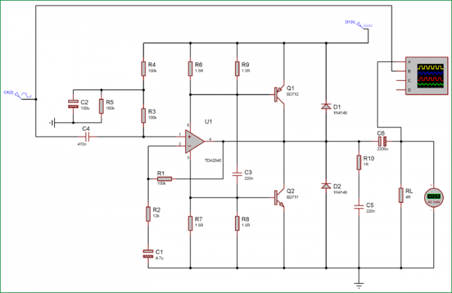
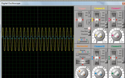
We use proteus simulation tools to check the output of the circuit; We can observe the output in a virtual oscilloscope.

The simulation results are shown in the following figure

Calculation of amplifier power
We can use a simple formula to calculate the power of an amplifier
Amplifier power=V squared/R
In the simulation tool, we connect an AC voltmeter at the output. The voltmeter shows the peak and peak value of alternating current.
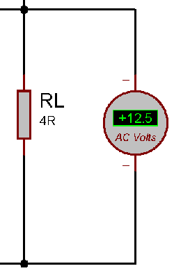
We input a low-frequency sine wave signal of 200Hz. Because at low frequencies, the amplifier will output more current on the load, so the multimeter can also accurately detect AC voltage.

We input a low-frequency sine wave signal of 200Hz. Because at low frequencies, the amplifier will output more current on the load, so the multimeter can also accurately detect AC voltage.
As shown in the above figure, the voltage is+12.5V, according to the above formula, and the load is 4 Ω, it can be obtained
Amplifier power=12.5 x 12.5/4=39.06 (close to 40W)
Precautions for building a 40W amplifier
When building a circuit, the power amplifier TDA2040 needs to be correctly connected to the heat sink. The larger the radiator, the better the result. Simultaneously using audio grade capacitors can achieve better results.
Meanwhile, it is best to use PCBs for audio related applications. But it is necessary to understand the following guidelines.
1. The audio signal wiring should be as short as possible to reduce unnecessary noise coupling.
2. The power transistor should be connected to a suitable heat sink.
3. Do not use a single heat sink to secure TDA2040, BD711, and BD712. Different components use different heat sinks, otherwise short circuits may occur.
4. Be sure to pay attention to the power of the speakers, otherwise they may be burned out.
5. Do not remove the buffer circuit. It plays a crucial role in protecting power transistors and amplifiers.
6. Do not apply amplified signals to the amplifier, as their THD will increase.
|
Disclaimer: This article is transferred from other platforms and does not represent the views and positions of this site. If there is any infringement or objection, please contact us to delete it. thank you! |


