Discussion on the Influence of Ground Wire on EMI Interference
Time:2023-04-27
Views:1055
As the functions of electronic products become increasingly complex, more and more modules and components are required. However, due to these reasons, our ground is constantly segmented. Although the four layer board can have a complete ground plane, we also need more through holes and unnecessary stray parameters, which are factors causing EMI problems due to the imbalance between these stray parameters and the ground.


The concept of two places
The traditional definition is that a voltage reference point is required for the normal operation of a circuit, which is called ground and the reference potential. Nowadays, with the popularization of electronic devices, the problem of electromagnetic interference is becoming increasingly serious. The terminology of ground is also becoming increasingly broad, such as filtering ground, shielding ground, backflow ground, safe ground, and various other terms. Overall, it refers to the return path of power supply current and signal current.
Reasons for interference caused by three ground wires
1. Imbalance of ground wire impedance When it comes to the impedance of a ground wire, many people come up with a typical specification, which is that the ground resistance should be less than 4 Ω. However, please note that traditionally, we mentioned that the grounding resistance should be less than 4 Ω, which is for safety purposes. A smaller grounding resistance ensures that excessive voltage will not occur in the event of a fault current and will not cause harm to the human body. In addition, a smaller grounding resistance ensures that a larger short-circuit current can be generated in the event of a short-circuit fault in the distribution system, triggering the protection device. This paper discusses the influence of ground impedance on electromagnetic compatibility of circuit system, not for the purpose of safety. So how does the impedance of the ground wire cause electromagnetic interference? Firstly, let‘s review the impedance of the ground wire.

Through the above formula, we can determine which parameters determine the impedance of the ground wire, RDC is the DC resistance value on the wire, and jwL is the inductive impedance. Due to RDC being ρ It is determined by three factors: (resistivity), S (cross-sectional area), and L (length). ρ The resistivity of the material is usually fixed after the wire is made, and the resistivity of copper is 1. So the resistance value that affects resistance in direct current is the cross-sectional area and length of the wire. According to the formula:

It can be seen that the magnitude and frequency of the AC resistance value also have a relationship. What are the factors that determine resistance?
According to the formula:

The factors that determine the inductance are mainly the length and diameter of the wire. Therefore, we also know the factors that determine the impedance of the wire, so the inconsistency of ground impedance in various parts of the circuit is determined by the above factors. So, let‘s take a look at how the imbalance of ground impedance generates electromagnetic interference.


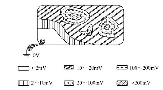
Figure 2 Real situation of ground wire potential
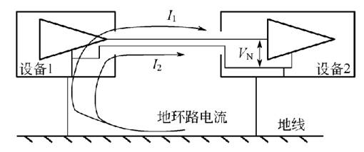
Our impression of Figure 2 is like the distribution of landforms on a geography book, but in fact, this is the distribution of ground impedance on a PCB board. It can be seen that different ground impedances correspond to different potentials. Therefore, our understanding is that the imbalance of ground impedance leads to a different potential between the ground and a potential difference between the two. This potential difference can be equivalent to a power signal, which generates a ground current under the impedance of the ground, which is what we call ground noise. The presence of ground noise can be radiated through some wiring harnesses or spatial radiation, so we cannot pass the test when testing CE or RE. 2. Interference of the ground loop. Ground loop interference is a common interference phenomenon that often occurs between devices connected by long cables that are far apart. The internal reason for its occurrence is the presence of ground loop current. In Figure 3, device 1- interconnection cable - device 2- ground wire forms a loop. It should be noted that sometimes the ground loop is not obvious, even if two devices are not connected to the same metal body at the same time, or even if both devices are not connected to the same metal body, the ground loop may still exist. Because there are stray capacitors between the device and the ground plane, these stray capacitors form the current path.

Figure 3 Formation of Ground Loop Interference
According to Figure 3, it can be seen that I1 and I2 form a loop through the parasitic capacitance between device 1 and device 2 and the ground. For the unbalanced circuit shown in Figure 2, I1 and I2 form a noise voltage VN after passing through the input impedance, which interferes with the circuit. four
The reason for the formation of loop current
When the grounding points of two devices are different, due to the different potentials of the two grounding points, a voltage is formed between the grounding points of the two devices, and under the driving force of this voltage, a ground loop current is formed, as shown in Figure 4. The formation of this ground wire voltage is due to the large current flowing through the conductor as the ground, which forms a voltage on the impedance of the conductor. The common mechanisms that generate this current include the working current flowing through the ground wire in buildings with poorly designed ground wires; An electrostatic discharge phenomenon has occurred on the cabinet, and the electrostatic discharge current flows through the overlap point on the cabinet; Lightning induces electrical currents on the shells of aircraft, ships, and other structures. The difference in ground potential caused by lightning discussed in the previous section is an extreme situation.
As shown in Figure 4, when the voltage on the grounding wire of a device is high, this voltage drives the ground loop current, which is common and usually caused by two reasons
(1) The surge discharge current flows through the ground wire. As mentioned earlier, in order to protect the equipment from surge voltage damage, it is necessary to install surge voltage protectors at the cable ports. When a surge voltage occurs on the line, the surge suppressor will act, bypassing the surge energy to the ground. The surge current (up to several thousand amperes) will generate voltage on the ground wire, which can be very high and even reach the level of interference with digital circuits.
(2) Electrostatic discharge current. When electrostatic discharge occurs on the casing, the discharge current will flow through the safety ground wire. Due to the high frequency of electrostatic discharge current, the ground wire exhibits a large inductance, resulting in a high ground wire voltage and serious interference problems.
When interconnected devices are exposed to strong alternating electromagnetic fields, according to the law of electromagnetic induction, the alternating magnetic field will generate an induced voltage V=l (dp/dt) in this circuit, where l is the inductance of the circuit and p is the magnetic flux. Under this voltage drive, loop current is induced in the loop formed by device 1- interconnection cable - device 2- ground,
V. Summary
The main reasons for the interference caused by the ground wire mentioned above are the imbalance of low impedance and the size of the ground circuit area. So when designing products, we need to consider how to draw and what kind of circuit is correct, which greatly reduces our later obsolescence and reduces certain costs
|
Disclaimer: This article is transferred from other platforms and does not represent the views and positions of this site. If there is any infringement or objection, please contact us to delete it. thank you! |


