The influence and selection of resistive and capacitive components on audio amplifiers
Time:2023-04-25
Views:1073
Resistive capacitance components are the most widely used passive devices in audio equipment. In recent years, domestic audio manufacturers have attached great importance to the selection of active devices such as integrated circuits (ICs), crystal transistors, field-effect transistors, and electronic tubes in the design of sound sources (CDs or DVDs) and power amplifiers. They have made significant progress in circuit design, product technology, and other aspects. However, there is a significant gap compared to European and American countries in the field of high value-added HI-END audio products. One of the reasons is that there is insufficient emphasis on the selection of passive components such as resistors and capacitors. In order to improve the playback effect of audio equipment, through the analysis and research of resistive and capacitive components, the same set of audio equipment and different resistive and capacitive components were compared and tested. It was found that the impact of resistive and capacitive components on audio equipment should not be underestimated. Reasonable selection of resistive and capacitive components can improve the performance indicators and playback effect of audio equipment.





The audio equipment mainly consists of a sound source (CD or DVD), a front-end equalization amplifier (amplifier front-end), and a back-end power amplifier (amplifier back-end). The audio amplification part of the above equipment basically adopts two modes: integrated block (IC) and discrete components. The integrated block mode is mostly composed of integrated operational amplifiers and resistive and capacitive components, while the discrete component mode is mostly composed of crystal transistors, field-effect transistors or electronic tubes and resistive and capacitive components. We have always attached great importance to the selection of active components such as integrated circuits (ICs), crystal transistors, field-effect transistors, or electronic tubes when designing audio equipment, while the selection of passive components such as resistors and capacitors is relatively casual. Many people believe that resistive and capacitive components have little impact on sound. Indeed, in low demand situations such as home theaters, computer stereos, and color TV audio circuits, ordinary resistive and capacitive components can be used; However, in high-end audio devices, it is necessary to carefully select components such as resistors and capacitors, otherwise it will be difficult to achieve the level of HI-FI or HI-END.
1 About Resistors
Resistors are the most frequently used devices in various circuits. In HI-FI or HI-END equipment, the selection of resistors will directly affect the performance indicators of the equipment, such as signal-to-noise ratio, fidelity, etc. The resistor entering the working state will generate noise, which depends on the resistance value, temperature, applied voltage, and resistor type. The total noise of the resistor is composed of multiple components. Closely related to various audio circuits are thermal noise and current noise.
1.1 Thermal noise of resistors
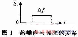
In resistors, due to the irregular thermal motion of electrons, there are irregular fluctuations in the instantaneous value of electron concentration within a sufficiently small volume, and the potential also undergoes irregular fluctuations. Therefore, a fluctuating potential difference is formed between any two small volumes of the resistor body, which is the thermal noise of the resistor. In terms of frequency characteristics, it belongs to white noise, that is, the spectrum is uniformly distributed, as shown in Figure 1. Within the bandwidth, the root mean square value of thermal noise can be expressed as
ST=4kTR△f…… (1)

In the formula, R is the resistance value of the resistor, in Ω; T is the temperature of the resistor, in K; k=1.380 7 × 10-23 J/K is the Boltzmann constant. The above equation indicates that the thermal noise of the resistor is independent of the resistor material and is proportional to the resistance value, temperature, and bandwidth. Thermal noise is an uncontrollable physical phenomenon that exists in any type of resistor and cannot be eliminated by changing the quality of the resistor.
1.2 Current noise of resistors
The current noise of resistors is directly related to the material, process, and type (nonlinearity) of the resistor. The nonlinearity of resistors reflects the degree of non density and discontinuity (heterogeneity) in the internal structure of the resistor material, thus to a certain extent reflecting the quality of the resistor. Through experiments, it was found that most resistors exhibit a certain degree of nonlinearity. For nonlinear resistors, the root mean square value of current noise can be expressed as:

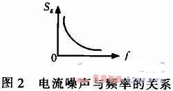
In the formula, K is a constant that depends on the material of the resistor component and its manufacturing process, U is the DC voltage drop at both ends of the resistor, △ f is the bandwidth, and is the signal frequency. The above equation indicates that within a certain △ f bandwidth, the current noise SE is proportional to the square of the DC voltage drop U on the resistor, and inversely proportional to the frequency. After U, R, and △ f are determined, the relationship between current noise SE and frequency f can be represented in Figure 2.

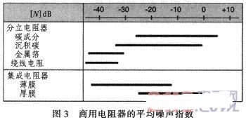
The current noise level in resistors is usually represented by the noise index [NI] dB

In the formula, u is the root mean square noise voltage on the bandwidth, while U is the DC voltage drop on the resistor, and both u and U are measured in V. The unit of [NI] is dB.
Figure 3 shows the average noise index of commercial resistors. In the figure, resistors based on composite resistive materials such as carbon and thick films have the highest current noise level. This is due to the significant heterogeneity of these resistive component materials. The conductive paths in these composite materials are formed by conductive particles in contact with each other in the isolation matrix. When current flows through unstable contact points in these ‘contact positions‘, they generate noise. Thin film resistors have a relatively strong homogeneous structure, resulting in low noise. Thin films are made by evaporating or splashing resistive materials on ceramic substrates

(For example, tantalum nitride TaN, silicon chromium SiCr, and nickel chromium NiCr) deposited. The noise level of metal foil resistors and winding resistors is the lowest. These two types of resistors are generally made of alloy materials, which have good density and uniformity, resulting in low noise; The noise mainly comes from the junction between the resistor body and the resistor pin, which may generate additional noise. However, the main drawback of wound resistors is their inductance, which requires special attention in use.
2 About capacitors
Under the action of alternating electric fields generated by audio signals, capacitors exhibit complex impedance properties. A capacitor can be equivalent to an RLC series circuit, as shown in Figure 4. In the figure, C is equivalent capacitance, L is equivalent series inductance (ESL), r is equivalent series resistance (ESR). It can be represented by the following impedance equation, namely

In the equation: ω= 2π

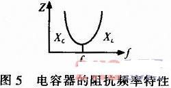
When the frequency of the audio signal increases, the capacitive reactance of the capacitor decreases and the inductive reactance increases, with XL>XC. The equivalent circuit exhibits inductance, and the higher the frequency, the greater the inductive reactance, as shown in the right curve in Figure 5; When the frequency decreases, the capacitive reactance increases and the inductive reactance decreases. When XC>XL, the equivalent circuit exhibits capacitance. The lower the frequency, the greater the capacitive reactance, as shown in the left curve of Figure 5; When f=f0, XC=XL, series resonance occurs in RLC circuit, and the equivalent impedance is r. Therefore, the impedance of the capacitor exhibits a U-shaped characteristic with frequency variation, as shown in Figure 5. From Figure 5, it can be seen that the upper limit of the operating frequency fH of the capacitor is<f0. When f ≥ f0, the capacitor has failed.

The existence of equivalent series inductance (ESL) has a negative impact on the performance of capacitors: 1) it limits the upper operating frequency of the capacitor, and the larger the equivalent inductance of the capacitor, the lower the operating frequency; 2) Affects or even changes the waveform of input pulse voltage; 3) Affects the speed of capacitor charging and discharging. 4) The equivalent series resistance (ESR) will bring losses to the capacitor.
For ceramic capacitors, they use ceramics as the dielectric of the capacitor. Due to the piezoelectric properties of ceramic materials, when the voltage at both ends of ceramic capacitor C changes, its capacity also changes. Taking a common 1000 pF ceramic capacitor as an example, according to testing, when the voltage at both ends of ceramic capacitor C changes from 0 to 15 V, its capacity C changes from 963 to 982 pF.

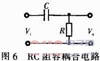
If a ceramic capacitor C is used to form an RC coupling circuit, as shown in Figure 6. At the input end, a sine wave is input. When the peak or valley arrives, the bias voltage of the capacitor is maximum, and at the 0 axis, the bias voltage is minimum. When a periodic signal passes through a capacitor, the capacity of the capacitor undergoes a process of change from small to large, and then from large to small. The output voltage expression of RC coupling circuit is:

If the input is a standard sine wave, the output waveform will undergo distortion, resulting in harmonic distortion, indicating that ceramic capacitors have nonlinear characteristics. Examining the above equation, within a certain frequency range, the higher the signal frequency, the smaller the capacitive reactance. When XC<<R, Vo=Vi, the influence of the capacitor can be ignored, and the output waveform is close to the input waveform. That is to say, ceramic capacitors have large low-frequency distortion, while high-frequency distortion is relatively small. The piezoelectric effect on voltage sensitive ceramic capacitors is the main cause of harmonic distortion. However, film capacitors that are not sensitive to voltage will also cause nonlinear distortion due to dielectric loss, equivalent series resistance, inductance and other factors, but the distortion is of a low order of magnitude, which is difficult for human ears to detect.
3. The impact of resistive and capacitive components on audio equipment
At room temperature, if the audio amplifier circuit in the sound source has a resistance value of 10 k Ω, then when the bandwidth of the audio equipment‘s sound source and power amplifier is 20 kHz, the thermal noise and electric heat of the resistance are about 1.5 μ V. Current noise is approximately 0.5 μ V. Approximately 2 in total μ V; At this point, assuming the voltage gain of the audio amplifier circuit of the audio source CD player is 20 dB, the voltage gain of the pre amplifier stage is 20 dB, the voltage gain of the post amplifier stage is 20 dB, and the total voltage gain of the audio equipment is 60 dB, that is, the voltage amplification factor is 1000 times, then the noise voltage output by the power amplifier is Vo=2 μ Vx1 000=2 mV。 As the temperature increases, the output noise voltage will be greater than 2 mV.
If the audio amplification part of the sound source adopts an RC coupling circuit, the harmonic distortion of the output signal of the sound source is 0.05%, and the total voltage gain of the front and rear stages of the power amplifier is 40 dB, that is, the voltage amplification factor is 100 times, then the harmonic distortion of the output signal of the power amplifier is 100x0.05%=5%. If ceramic capacitors are used, harmonic distortion will be greater. In addition, the equivalent series resistance and inductance of the capacitor will also affect the charging and discharging speed of the capacitor, causing the transient distortion of the audio signal.
For ordinary audio equipment, the output noise voltage is 2 mV and the harmonic distortion is 5%. It is not easy for ordinary people to notice, and for ordinary users, it is acceptable in situations with low requirements. But for HI-FI or HI-END audio devices, it cannot be tolerated. Because HI-FI or HI-END audio devices require a very quiet background and high performance indicators, even a noise voltage of 2 mV can affect the quietness of the background, let alone 5% harmonic distortion.
4. Selection of resistive and capacitive components
4.1 Selection of Resistance Elements
In order to ensure the high fidelity of FI or HI-END audio equipment, according to the above analysis, metal film resistance or film resistance should be considered for the sound source, front and rear power amplifiers, and non inductive ceramic resistance can be used for the high current part; The resistance error should be small, and the nominal power of the resistor should be greater than the actual power consumption, generally not less than twice the actual power consumption, in order to reduce the temperature of the resistor, reduce the thermal and current noise of the resistor, and improve the signal-to-noise ratio of the audio equipment. At present, the performance of resistors and capacitors produced in European and American countries is better than that of domestically produced ones, such as the US DALE military resistor and the Western Electric porcelain pipeline winding precision resistor, which have stable performance and are used for power filtering and cathode resistance, with good sound quality and low noise; Xidian (Black Spareribs) precision resistor, used as a single ended power amplifier tube 300B, FU50 biliary cathode resistor, has stable performance and excellent sound quality. Another example is the French metal film resistor, which has high accuracy and an error of less than 1%. It is used for matching resistors in audio systems with good consistency, high balance, crystal clear and delicate sound quality, and low noise.
4.2 Selection of capacitive components
For capacitors, 1) try not to use capacitors if possible, 2) do not use ceramic capacitors, and 3) when capacitors are needed, select capacitors with low equivalent series resistance and inductance ESL, low dielectric loss, small leakage current, and good high-frequency performance (high f0). The nominal parameters of a capacitor, 1) capacitance, are the values marked on the outer shell of the capacitor, commonly used μ F. PF represents, 2) safe working voltage (referring to the nominal value of the working voltage of the electrical container), and the actual working voltage is about 2/3 of the rated nominal value, which is relatively reasonable and reliable. Generally, the higher the nominal voltage, the smaller the leakage current; 3) The common temperatures are mostly 85 ℃ and 105 ℃. Under high temperature conditions (such as electronic tube amplifiers or pure Class A transistor amplifiers), capacitors with a nominal temperature of 105 ℃ should be preferred. In general, choosing capacitors with high temperature coefficients can also help improve other performance, and it is best to choose audio specific capacitors. For example, the Danish JENSEN aluminum foil capacitor, copper film capacitor, copper tube capacitor, the American SPRAGUE capacitor, the SPIVITAMIN Q oil immersed capacitor, the famous German ROE electrolytic capacitor, and the Japanese ELNA capacitor have their own characteristics.
In audio circuits, organic, inorganic dielectric capacitors and electrolytic capacitor are mostly used. After selecting the circuit, capacitors are still one of the main factors affecting the sound quality and timbre of the amplifier. Replacing different types of capacitors in the same circuit can result in different changes in sound quality and timbre. This is because different capacitors, although their capacity and withstand voltage are the same, have different manufacturing processes and materials, resulting in significant differences in inherent dielectric loss, insulation resistance, dielectric charge discharge rate, and series equivalent inductance. In order to avoid the negative impact of capacitors on signal transmission, it is best to design the inter stage coupling of the audio amplification circuit as a direct current coupling (DC) circuit; For electronic tube audio amplifiers that cannot use DC coupling, high-quality capacitors such as SOLEN from France and VIMA from Germany should be used for inter stage coupling. This capacitor has first-class quality, with a capacity error of less than 3%, its own inductance is less than 50 nH, and its harmonic distortion (THD) is less than 0.001%, making it very suitable as an interstage coupling capacitor. If SOLN or VIMA small capacitors are connected in parallel at both ends of electrolytic capacitor for power filtering and decoupling, the high-frequency interference brought by the power grid can also be effectively suppressed.
5 Conclusion
In summary, resistive and capacitive components have an impact on the sound quality and color of HI-END level (advanced) audio amplifiers. Experienced audio enthusiasts can achieve certain results by replacing some high-quality audio specific resistive and capacitive components for CD players or audio amplifiers with average sound quality and color performance. At present, audio manufacturers in European and American countries are gradually adopting chip mounted resistive and capacitive components to reduce the adverse effects caused by resistive and capacitive components, and the effect is quite obvious.
|
Disclaimer: This article is transferred from other platforms and does not represent the views and positions of this site. If there is any infringement or objection, please contact us to delete it. thank you! |


