New brushless DC motor control sensor improves energy efficiency and reduces noise
Time:2023-03-17
Views:1145
Brushless DC (BLDC) motors have increasingly become the main force in the motor market. Although the procurement cost is a little high and electronic devices need to be controlled, compared with traditional brushless motors, brushless DC motors have some main advantages: high efficiency, wear resistance, long service life, compact design, high power density, low noise, and improved reliability. Effective control requires high-performance feedback sensors to sense the position of the rotor. The new generation of Hall switch and angle sensor from Infineon can provide excellent motor control function and reduce motor energy consumption.

The rotor of brushless DC motor has a permanent magnet and the stator has a winding. The direction of current in different windings is no longer reversed by sliding (commutation) on the brush through mechanical commutator, but reversed by electronic method.
Accurate and sensitive position sensors are required to control the stator winding and electronically sense the position of the rotor. Block commutation (e.g. using Hall switch) and (magnetic) field-oriented commutation have essential differences. Unlike the block commutation using discrete switching points, which needs to sense the sector transition of the rotor, the field-oriented commutation used for high dynamic load or precise drive needs to continuously obtain the position information and extremely accurately understand the rotor position. For example, this can be achieved by using angle sensor or sensorless method. For sensorless technology, the rotor position is calculated by the change of the induced reverse voltage. This algorithm increases the cost due to the use of single-chip microcomputer and software algorithm. In addition, another disadvantage of this technology is that it cannot provide reliable information before the rotor reaches a certain speed. Therefore, compared with BLDC motors with sensors, sensorless BLDC motors have poor starting characteristics.
Block commutation
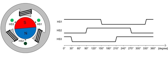
For block commutation, rotor position feedback is usually provided by three Hall sensors (one sensor for each stator winding) installed in the motor. The bipolar control magnet and the Hall sensor with a phase difference of 120 ° can provide six different switch combinations at each rotation (Fig. 1). According to the information provided by the sensor, three partial windings are started in six different control stages. The change curve of current and voltage is blocky. The output signal of the sensor provides a digital image, which can control the winding with less logic operation. Therefore, there is no need to use complex algorithms for control. In the simplest application, block commutation can be realized without a single chip computer. Therefore, the advantages of this technology are the use of relatively simple and low-cost electronic devices, high accuracy, control of starting and high starting torque. The TLE4961 or TLE4968 Hall switch newly launched by Infineon can realize efficient BLDC motor block commutation through accurate magnetic switching points and accurately sense the rotor position.

Figure 1: BLDC motor with Hall switch can perform block commutation
Accurate Hall switch
As mentioned earlier, for block commutation, the three Hall switches are located around the rotor, with a phase offset of 120 ° from each other. They can identify the south and north poles and provide output voltage with logic 0 or logic 1 accordingly. The position of the rotor can be determined in a 60 ° sector according to the logic status of all three Hall switches. According to this information, the rotor winding is switched accordingly. In order to achieve this operation, the sensor must be able to accurately detect the position of the rotor. Ideally, the sensor should be able to provide commutation signal independent of torque. A decisive criterion of sensors is the phase fidelity of their switching, otherwise the phase offset will occur when switching between winding and rotor positions. Phase offset can cause greater torque ripple, generate greater noise and increase energy consumption.
However, due to the influence of manufacturing, each sensor has specified magnetic switch point tolerance. As the temperature increases, the magnetic field strength of permanent magnet in BLDC motor decreases. The fluctuation of mechanical stress and temperature will produce drift effect. In order to achieve accurate Hall sensor switch, these effects must be compensated.
Temperature compensation circuit of magnetic field switch threshold. The switch threshold can be adjusted according to the temperature. The sensor can compensate the temperature related field strength change of the magnet. The "rotating Hall probe" structure of the Hall element can greatly reduce the shift of the switch threshold, thus improving the overall stability of the switch. With this signal processing function, the time between measuring and switching the output signal is slightly increased, but this delay is constant, and the holding time depends on the speed of block commutation.
This new Hall chip with integrated compensation circuit has stable temperature characteristics, thus reducing the impact of technical changes. Active error compensation (a rotating Hall probe technology) can compensate for the influence of signal path offset and mechanical stress of Hall element. In addition, the Hall switch has very low jitter (<0.3 μ s)。 The output transistor also has over-current and over-temperature protection functions.
Field-oriented commutation
Block commutation does have a conceptual disadvantage. Since it is divided into six sectors, the winding is continuously switched on and off during 60 ° rotation (that is, the force and magnetic line of force can be generated only when the maximum energy efficiency is reached, and each other is kept at 90 ° for a short time). Before the conversion point, the force and magnetic force line vector are only related at 60 °, in which case the energy efficiency is reduced to 87%.
The magnetic field generated by the stator improves this situation, and the stator rotates at the same speed as the rotor: the forces and magnetic lines of force are completely parallel to each other. This is because the winding no longer uses the sector-based method, but uses the pulse excitation method to switch, so the sum of different winding magnetic fields at the rotor position produces an excellent permanent total magnetic field. Finally, the winding generates a sine wave current, which means that the torque and magnetic field are always parallel. This field-oriented program has many advantages, such as extremely low noise level, very stable torque, and variable speed excitation. However, the premise is that the rotor position can be measured extremely accurately, which cannot be achieved by Hall switch alone, and precise angle sensor is also required.
Precise angle sensor
For field-oriented commutation, the angle sensor must be able to accurately determine the position of the magnet in the entire life cycle of the product, regardless of temperature and speed. TLE5009/TLE5012B series angle sensors can quickly update the measured data, and the delay is very short, thus improving the efficiency - even in the case of high speed and load changes.
This high-precision angle sensor is located in front of the rotor shaft end. An outer diameter magnet is installed on the rotor shaft end nearest to the motor bearing. The angle sensor can reliably detect the rotation of the magnetic field.


Figure 2: Application example of angle sensor
The new angle sensor is based on the innovative iGMR (integrated giant magnetoresistance) technology. By providing amplified analog interface, the cost efficiency is greatly improved, while highly integrated and multifunctional ones have strong data processing functions, and several optional digital interfaces are provided.
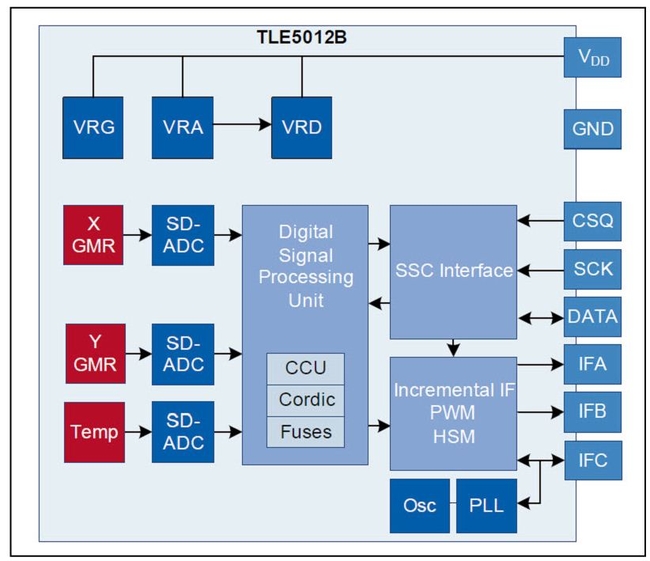
A new benchmark for short delay and high signal resolution. It can provide an angle accuracy of 1 ° and a resolution of 15 bits in the whole operating range, and can achieve an accuracy of 0.6 ° at room temperature. In addition, TLE5012B can also consider internal time extension through measurement and comprehensive processing of measurement data. That is, the sensor knows the rotational speed and can independently add the rotation angle during the generation of measurement data to the output value. In addition, TLE5012B can be selected by the user: SSC, PWM, Incremental Interface (IIF), Hall Switch Mode (HSM) and Short PWM Code (SPC).

Figure 3: Highly integrated and precise angle sensor can perform a variety of signal processing, thus reducing the load of single chip computer.
Conclusion
The new TLE496x series hall switch and angle sensor are powerful sensors that can be applied to BLDC motor drive. Depending on the mechanical layout, space requirements, the location of the motor electronics and the required accuracy, the ideal solution for any application can be selected from these sensors. The TLE496x switch allows designers to design economical and compact products. Compared with discrete solutions (i.e. with sensor bridge, Hall element, signal amplifier and compensation software), the TLE5009 has great cost-saving potential and does not need to change the system concept. The highly integrated TLE5012B with integrated signal processing function can also make the single chip computer unnecessary to realize accurate angle calculation and complex calibration algorithm.
Phase-locked hall switch
The new hall switch TLE4961 (phase-locked switch) and TLE 4968 (bipolar switch) can operate in the voltage range of 3.0 – 32V. Without the need for additional external resistors, they can withstand voltages up to 42V. Their magnetic switching point (Bop=+/- 1mT) has extremely high sensitivity and reliability. Due to the integrated error compensation circuit, they have extremely high resistance to mechanical stress. Their output devices also have overvoltage and over-temperature protection functions. Moreover, they have high anti-static capacity (+/- 7kV HBM). The jitter at normal speed is about 0.3 μ s。 The rated power consumption is 1.6mA, which is especially suitable for energy-saving design. Small SOT23 packages can be provided, and their board area is 22% smaller than that of ordinary SC56. They are also available in lead-containing SS0-3 packages.
Precise angle sensor
The angle sensor is based on iGMR technology. They can measure the magnetic field parallel to their packaging surface in the direction of 0 ° - 360 °. This iGMR sensor has extremely accurate angular resolution, fast signal processing capability and short delay/update time. This makes them extremely suitable for accurate determination of rotor position in high dynamic applications. TLE5012B can be equipped with different interfaces (selected by the user), which creates conditions for realizing the design with extremely reliable functions. In order to achieve this goal, the equipment also has advanced self-test and status monitoring functions, as well as special architectural features. For example, each of the two integrated Wheatstone sensor bridges has an independent data channel.
|
Disclaimer: This article is transferred from other platforms and does not represent the views and positions of this site. If there is any infringement or objection, please contact us to delete it. thank you! |


