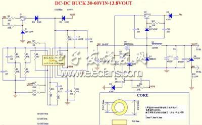
Buck DC-DC converter with high voltage input
Time:2023-03-03
Views:1218
describe
Most common DC-DC applications are suitable for lower Vin/Vout voltage (less than 30V-40V). It is rare for higher voltage input. This paper introduces a step-down converter with TL494 as the controller and can work at 60V input.
It can be used for higher voltage by properly modifying the part specification. This circuit works at 110 Khz, and its efficiency is higher than 80%. The output current can be 0-2.2A, and the driving voltage of MOSFET (IRFW630A) is taken from the bootstrap circuit, so that the gate signal can always be about 10V higher than the input voltage. The advantage of using MOSFET is that it can work at high frequency and reduce the loss during conduction. The high working frequency of the circuit also reduces the volume of the inductor.
Component selection:
D7 should use UHF fast recovery diode, here HER303 is used, HER304-307 can also be used, but the conduction voltage drop is slightly higher. For Schottky diode, select the model with withstand voltage greater than the maximum input voltage;
For C11 and C12, capacitors that can work at high frequency and have low ESR will be selected, and the capacitance at low frequency will even be obviously heated and quickly damaged, and the ripple is also very large;
The common 2N5551 is used for all small triodes, with withstand voltage of 150V, and switching speed is acceptable;
For MOSFET selection, the withstand voltage is higher than the maximum possible input voltage, and the smaller the on-resistance is, the better, for example, VINmax: 50V, 60N06;
Power inductor: use common yellow-white iron powder magnetic core (outer diameter * inner diameter * thickness: 13 * 7.5 * 6.5). 0.4mm enamelled wire is wound with three wires for 50 turns, and the inductance is about 120UH. Note that the black core can not be used here (large inductance is easy to fill).
This inductance is only suitable for the conditions of the drawing. Please change it yourself if there are major changes.
The protection diode is not small. If the switch tube breaks down, VOUT=VIN, it will directly damage the load! With a 1W voltage regulator, the nominal voltage is several V higher than the output voltage. The safer way is to use a unidirectional thyristor plus a voltage regulator and a resistance protection circuit.
other:
Output voltage setting: R9
Output current limit: R5
Maximum duty ratio setting: R3 (without R3, the duty ratio can reach the maximum, suitable for the case of small input and output pressure difference)

|
Disclaimer: This article is transferred from other platforms and does not represent the views and positions of this site. If there is any infringement or objection, please contact us to delete it. thank you! |


