Ripple Reduction Technology for Stable Power Conversion
Time:2023-01-10
Views:1408
Key points of this article:
• Ripple is noise on the power supply.
• To provide a stable power supply, it is necessary to reduce the ripple of the output voltage.
• Ripple reduction techniques include filtering and precise feedback adjustment.
All power supplies have a certain degree of ripple, which is noise on the output port of the equipment. Especially in the output of switching DC-DC converter, ripple is a troublesome noise problem. In some applications, especially for analog devices receiving DC power supply voltage, a very "clean" power supply is required, otherwise the noise may spread to the output of the device. In contrast, saturation logic (such as TTL and CMOS) is more capable of resisting such noise.

The DC-DC converter with switch regulation needs to implement at least one ripple reduction technology, but the technology needs to match the appropriate switching frequency, power output and load operating frequency. The load impedance will also affect the determination of the switching converter behavior and the effectiveness of the implemented ripple reduction techniques. This paper briefly introduces several ripple reduction technologies and their best applications in new power supply design.
Ripple reduction technology: simple version and advanced version
Ripple reduction technology can be implemented through passive or active circuits, as well as linear or nonlinear devices. Some algorithms implementing the active control strategy try to compensate the ripple of the DC-DC converter output. The process may be a bit complicated, and it is best to use a dedicated ASIC to implement it.
Adjust with LDO
This strategy is an entry-level ripple reduction technology, which is suitable for devices using DC power. Many digital devices include an on-chip low dropout (LDO) linear regulator for reducing ripple, which can provide ripple reduction effect of about 80dB, which means that the ripple can be reduced by 100 million times! The principle of this design is to use a comparator and a stable silicon bandgap reference voltage source in the device to saturate the output voltage. However, this method reduces noise by saturation, so when the input voltage difference and output power are too high, the device will generate a lot of heat.

Linear regulator can greatly reduce ripple
wave filtering
Filtering with low-pass filter or notch filter is a strategy to solve the problem of ripple frequency. This method is effective in DC voltage regulator, especially when filtering is implemented. Simple high-order passive filtering implemented in pi (LC circuit) can provide a high roll off coefficient in the transfer function, but requires a very large inductance and capacitance to filter out the typical PWM frequency. A more complex strategy is to use active filtering technology to add reactance to the feedback loop, which can provide very high DC gain and suppress AC output.
feedback control
The feedback loop is implied in some highly integrated switching regulator devices, especially those that implement PWM oscillator, gate driver and FET stage in the same package. For more advanced designs operating at very high power outputs, a set of discrete devices is needed to implement the control strategy of the feedback loop. Once the ripple on the output can be sensed together with the DC output, the control strategy that can adjust the PWM drive signal and drive frequency can stabilize the output level and ripple at the same time. Power system designers have made active research in this field.
Larger inductor and higher PWM frequency
These two methods should be mentioned at the same time, because they are standard tools for setting the initial ripple value in switching regulators (in standard step-down, step-up, and step-down boost designs). The ripple level is inversely proportional to the output inductance and PWM frequency, so increasing them will reduce the ripple measured on the output port.

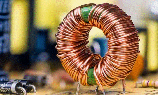
At low switching frequency, large inductors are needed to achieve the target ripple value.
Polyphase regulation
The polyphase converter realizes multiple switch stages in parallel, but they are separated from each other in phase. Although these circuits may be much more complex, they act like single-stage regulators, with larger switching frequencies and inductors. The result is that the ripple measured at the output is greatly reduced. As long as the cut-off frequency of the output filter stage is higher than the baseband frequency, these regulators can be used for DC load or high-frequency AC load of FM signal. These converters can also provide high current without putting too much pressure on the device because switching loads are distributed across multiple switch stages.
Summary of Ripple Reduction Technology
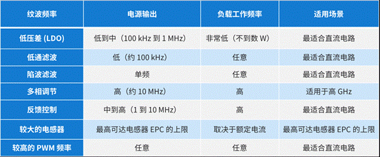
The following table describes the conditions under which various ripple reduction technologies are suitable for switching DC-DC converters. Designers should pay attention to using various methods to achieve ripple reduction, because if used in the wrong circumstances, the corresponding mechanism may fail.

The last point to consider is that these methods are often implemented together in new designs. For example, the step-down converter for RF power supply systems and high-power RF transmitters can use high-order low-pass filtering, polyphase regulation and high PWM frequency (several MHz or higher), and adopt passive or active control methods in the feedback loop. Selecting the right technology mix requires consideration of various factors, from the behavior of the load to the operation at the converter level. To evaluate these designs, start with SPICE simulations with high-precision device models.
|
Disclaimer: This article is transferred from other platforms and does not represent the views and positions of this site. If there is any infringement or objection, please contact us to delete it. thank you! |


