The target is that the revenue will exceed 250 billion yuan in 2025! Shenzhen‘s integrated circuit industry plan is expected to be released in the near future
Time:2022-12-31
Views:1401
A double pass band filter consisting of two H-resonators in edge coupling mode is designed. A dual frequency resonator is formed by bridging a microstrip line between two parallel microstrip lines. With the increase of the feed position and the middle microstrip line spacing, the two external quality factors of the dual frequency resonator change in opposite trends. With the increase of the spacing between the two resonators, the corresponding two coupling coefficients between the dual frequency resonators gradually decrease. Based on this feature, two resonators can be combined to form a double pass band filter.

With the development of wireless communication technology, the combination of mobile communication and wireless network applications has become a trend. Therefore, microwave dual pass band filter is more and more widely used and becomes an important device in wireless communication systems. Microstrip dual pass filter has been widely studied because of its small size and easy integration on the circuit board. At present, the research of microstrip double pass band filter mainly uses stepped impedance microstrip lines to form a dual frequency resonator. The double pass band filter is obtained by combining and the two single pass band filters are combined to form a double pass band filter. In this paper, it will be discussed that the H-type resonator composed of uniform microstrip lines can realize dual frequency resonance. By adjusting the position of the middle microstrip line near the opening, it is convenient to adjust the first resonant frequency, while the second resonant frequency is almost unchanged. The double pass band microwave filter can be formed by combining two resonators in electromagnetic coupling mode.
1 Theoretical analysis
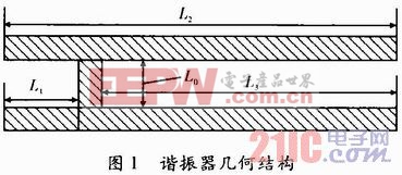
H-type resonator is a uniform microstrip line structure, as shown in Figure 1. The middle microstrip line is placed near the opening to realize dual frequency resonance, and the length of the microstrip line is 1/2 wavelength of each resonant frequency.

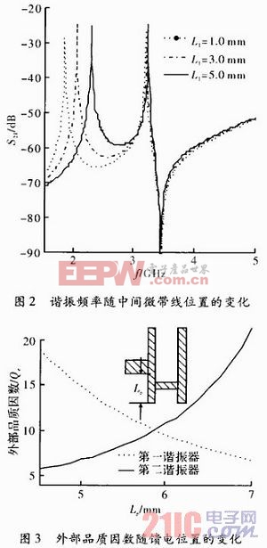
The right U-shaped microstrip structure is a low frequency resonator, namely, the first resonator, to achieve the first resonant frequency, and the upper and lower straight microstrip lines are high frequency resonators, namely, the second resonator, to achieve the second resonant frequency. Near the opening, adjust the middle microstrip line to move inward, then the first resonant frequency gradually increases, while the second resonant frequency changes slightly, and the two resonant frequencies gradually approach, as shown in Figure 2.

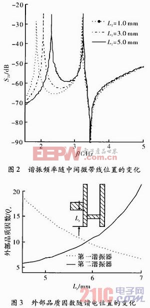
The filter is fed by tapping. When the position of the middle microstrip line is fixed, and the feed position moves upward relative to it, the two external quality factors corresponding to the dual frequency resonator change in opposite trends, as shown in Figure 3.

Electromagnetic hybrid coupling is adopted between resonators to enhance the coupling strength between resonators. When the distance between the two resonators is within a certain limit, the coupling strength of the high-frequency resonator is less than that of the low-frequency resonator, and when the limit is exceeded, the coupling strength is greater than that of the low-frequency resonator. The variation trend of coupling coefficient between resonators with spacing is shown in Figure 4.

2 Design and simulation of double pass band filter
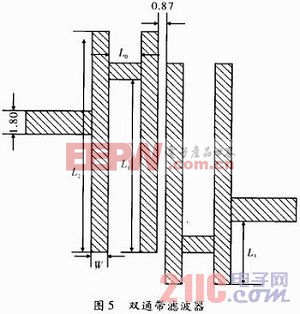
In combination with the above resonator unit structure, the two resonators are combined in the form of opposite opening directions, and a dual pass band filter is formed through electromagnetic edge coupling, as shown in Figure 5.
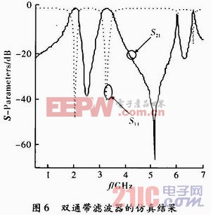
The bandwidth of the filter is determined by the external quality factor and the coupling coefficient between resonators. From the curve of the external quality factor changing with the position of the feed point in Figure 3 and the curve of the coupling factor changing with the distance between the resonators in Figure 4, it can be seen that adjusting the distance between the two resonators near the intersection of the two external quality factors can obtain appropriate electromagnetic coupling and realize the dual pass band filter. Rogers RT6006 material is used as the substrate. Its relative dielectric constant is 6.15, thickness is 1.27 mm, and the line width of microstrip feeder is 1.8 mm, so that the characteristic impedance is 50 Ω. Other dimensions of filter: W=1.0mm, L0=2mm, L2=21mm, L1=13.2mm, L3=6.0mm, S=0.87mm. The resonance frequency of equation (1) and (2) is about 1924 MHz and 3440 MHz. Sonnet is used for simulation, and the results are shown in Figure 6.

The center frequencies obtained are 1 994 MHz and 3 272 MHz respectively, and the minimum values of center bandwidth insertion loss are 0.39 dB and 0.35 dB respectively. A transmission zero is introduced between the two passbands to enhance the isolation of the two passbands. There is a transmission zero point outside the two passbands to enhance the out of band suppression capability. Because the two arms of the resonator are close to each other, there is a large electromagnetic interference between them, which makes the two resonant frequency points of the resonator offset from the theoretical calculated value.

3 Conclusion
H-type resonators are analyzed, and two resonators are combined to form a double pass band filter. By adjusting the position of the middle microstrip line, the center frequency of the first passband of the filter can be adjusted conveniently without changing the center frequency of the second passband. This double pass band filter is easy to design and manufacture.
|
Disclaimer: This article is transferred from other platforms and does not represent the views and positions of this site. If there is any infringement or objection, please contact us to delete it. thank you! |


