Brushless DC Motor for Industrial Automation
Time:2022-12-16
Views:1446
Industrial or factory automation is one of the fastest growing terminal applications of BLDC motors in the industrial subdivision field. As factories turn from more traditional brush or step motors to BLDC for higher efficiency and performance, the demand for three-phase grid drivers is also growing. Multiple motors are used in the design of terminal applications such as factory robots and cooperative robots.


NCD83591 is a 60V, 3-phase grid driver designed for brushless DC (hereinafter referred to as "BLDC") motor applications. It integrates three independent half bridge drivers and a detection amplifier to provide an easy-to-use grid driver. With its small package size and grid drive architecture, the scheme provides high power density and is easy to use, making it an ideal choice for industrial applications. The maximum input voltage of NCD83591 is 60 V, which provides sufficient margin to drive motors with rated voltages of 12 to 42 V, and is suitable for most industrial automation applications. In addition, NCD83,591 has the high power density and ease of use that industrial customers attach great importance to, providing an ideal solution for these applications.
power density
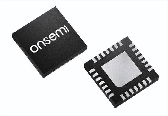
The NCD83591 is packaged in a 4 mm x 4 mm QFN-28 package and includes an integrated, fully configurable current detection amplifier, a lower bridge 14 V regulator, and an upper bridge charge pump. The product is the industry‘s smallest 60V, 3-phase grid driver, integrated with at least one detection amplifier. The compact package size and single integrated amplifier provide a perfect BLDC motor drive solution for space oriented applications. The product supports customers to quickly implement trapezoidal commutation to drive the motor, while minimizing the number of external components to achieve small program size. Compared with the discrete scheme using traditional independent half bridge driver IC, the integrated three-phase half bridge driver significantly reduces the size.

Figure 1: NCD83591 IC
Easy to use - ladder motor control
NCD83591 grid driver uses a single integrated amplifier, which is an ideal product for trapezoidal motor control commutation. This method is the most common BLDC commutation method in the industrial market, and is the best balance point between the optimal torque and design simplicity. Although field oriented control (FOC) and direct flux control (DFC) commutation methods are increasingly popular in more complex motor control applications, trapezoidal commutation is still the standard in the 12 to 40 V BLDC industrial market from an ease of use perspective.
Easy to use constant current grid drive
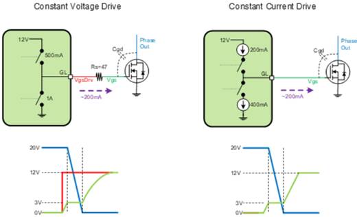
The grid drive architecture is another advantage of using the NCD83591 three-phase grid driver. The product realizes constant current grid drive instead of traditional constant voltage grid drive. Constant current drive provides the same switching network (motor phase winding) conversion time, but saves the cost of series grid resistance, and the drive circuit is smaller. It also helps to prevent self conduction without having to connect grid resistors in series. See Figure 2 below for more details. However, the most significant advantage of constant current gate drive is that the IC can sense the actual gate source (Vgs) voltage of the FET it drives. The grid detection function makes the NCD83591 stand out in terms of ease of use because it can realize the benefits of dead time optimization and true cross conduction protection.
The dead time is usually programmed into MCU to turn off the FET of one phase and then turn on the FET of the other phase. Programming usually allows additional time to ensure that cross conduction does not occur, as the timing changes with temperature, power, and aging. NCD83591 can detect the gate source voltage and turn on the opposite FET in the same phase after the FET is turned off. This eliminates the need to program the dead time of MCU, because the IC will process it, so as to minimize the dead time during pulse width modulation (PWM) and not be affected by delay. This product can also detect the external fault that supplies power to FET. When FET should not be enabled, disable the opposite side FET in the same phase to make corresponding response.

Figure 2: Constant current and constant voltage grid drive
|
Disclaimer: This article is transferred from other platforms and does not represent the views and positions of this site. If there is any infringement or objection, please contact us to delete it. thank you! |


