Principle of Inductive DC-DC Booster
Time:2022-11-23
Views:1552
This paper introduces the principle of inductive DC-DC booster, which belongs to the basic nature, and is suitable for those students who do not understand the characteristics of inductance, but are interested in the boost circuit at the same time.
If you want to fully understand the principle of inductive boost, you must know the characteristics of the inductor, including electromagnetic conversion and magnetic energy storage.
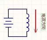
Let‘s first observe the following figure:

This figure shows that the battery energizes an inductor (coil). The inductor has a characteristic - electromagnetic conversion. Electricity can be changed into magnetism, and magnetism can also be changed back into electricity. At the moment of power on, electricity will become magnetic and stored in the inductor in the form of magnetism. The power off instantaneous magnetism will become electricity and be released from the inductance.
However, there is a problem. After the power is cut off, the circuit has been disconnected, and there is no place for current. How can magnetism be converted into current? Quite simply, there will be high voltage at both ends of the inductor. If the self inductance coefficient of the inductor coil is large, the self induced electromotive force will be large. In the gap between large potential differences, strong electric fields will be generated, and even air will be broken down, causing discharge. If there are people nearby, it will cause a certain danger. If there are flammable substances nearby, there is a risk of fire.
In this way, we also understand the second characteristic of the inductor - boost characteristic. When the circuit is disconnected, the energy in the inductor will be converted back to electricity in the form of high voltage.
Now let‘s summarize the above contents:
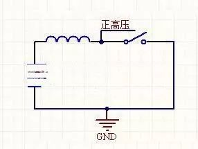
The following is a positive voltage generator. You can get an infinitely high positive voltage from the nodes in the figure by constantly flipping the switch. How high the voltage rises depends on what you connect to the other end of the diode to allow the current to flow. If nothing is connected, the current will have nowhere to go, so the voltage will rise high enough to break down the switch, and the energy will be consumed in the form of heat.

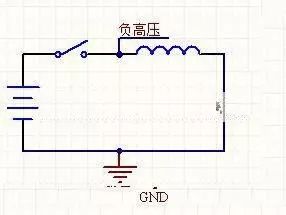
Then there is the negative pressure generator. You can get infinitely high negative voltage from the nodes in the figure by constantly flipping the switch.

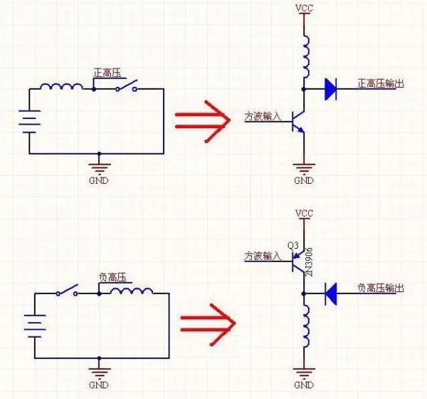
All the above are theories. Now let‘s look at the actual circuit to see what the minimum system of DC-DC boost circuit looks like.

You can clearly see the evolution. In the circuit, the switch is replaced by a triode, and the voltage can be boosted by controlling the switch of the triode with a square wave of fixed frequency. Don‘t underestimate these two figures. In fact, all switching power supplies are transformed from the combination of these two figures.
Finally, let‘s talk about magnetic saturation.
We already know that inductors can store energy in a magnetic field, but how much can they store? What happens when they are full?
Maximum magnetic flux. This parameter indicates how much energy can be stored in the inductor. According to this parameter, you can calculate the frequency at which an inductor must operate to provide n V mA current.
What happens when the deposit is full? This is the problem of magnetic saturation. After saturation, the inductor loses all the characteristics it should have, becomes a pure resistance, and consumes energy in the form of heat.
Inductance family
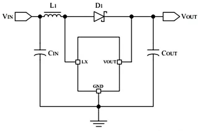
Application example: Booster chip E50U, E50D, E50P (PL2303) is a high efficiency, low ripple DC-DC converter with built-in MOS switch. The PL2303 series products only need 4 peripheral components, which can transform the voltage above 0.9V to 5V, and are often used in battery powered children‘s toy circuits.

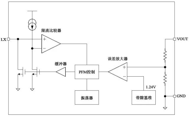
The typical booster circuit is the internal circuit of PL2303. It can be seen that the function of this VOUT pin is not "out", but "in". It detects the voltage of the VOUT for feedback.

Selection of the internal structure inductance of the PL2303: The operating frequency of the PL2303 is up to 300KHz. The purpose is to reduce the size of the external inductance. Only an inductance of more than 4.7uH is required to ensure normal operation. However, if the output terminal needs to output a large current load (for example, the output current is greater than 50mA), it is recommended to use a large inductance to improve the working efficiency. Considering comprehensively, it is recommended to use an inductor with 47uH and parasitic series resistance less than 0.5 Ω. If we need to improve the efficiency under heavy load, we need to use inductors with larger inductance and smaller parasitic resistance. The diode used for rectification has a great impact on the efficiency of DC DC. Although ordinary diodes can also make the circuit work normally, they will reduce the efficiency by 5~10%. Therefore, it is recommended to use Schottky diodes with low forward conduction voltage and fast reaction time, such as 1N5817, 1N5819, 1N5822, etc. As long as the power supply is stable, the circuit can output low ripple and low noise current and voltage even without input filter capacitor. However, when the power supply is far away from the DC-DC circuit, it is recommended to add more than 10uF filter capacitor near the DC-DC input terminal to reduce the output noise.
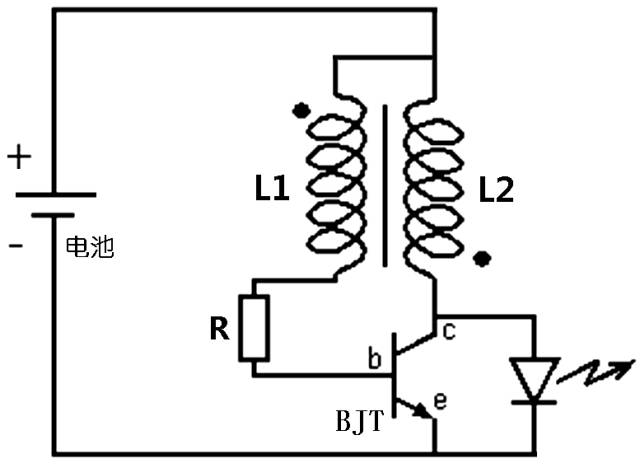
Joule Sneaker circuit is a simple self-excited oscillation boost circuit with low cost and easy fabrication. It can drain all the energy on a waste dry battery, even those batteries that are considered dead in other circuits. When making the Joule Sneaker circuit, you must pay attention to the opposite direction of the two inductors.

The standard Joule Sneaker circuit usually has a voltage of about 1.1V after the 1.5V dry battery is used up, indicating that there is still energy in the battery at this time, but the internal resistance has become very large, the output current is very weak, and it can no longer drive ordinary circuits, let alone light the LED. The Joule Sneaker circuit can generate high-frequency pulse voltage through the magnetic induction coil to make the LED conductive. By adjusting appropriate parameters, the battery voltage can be increased by more than 10-100 times. Joule Sneaker Principle 1. The current flows into the base of BJT through L1, making BJT start to conduct, the collector generates current, and the coil L2 at the collector terminal generates variable magnetic flux, making the base coil L1 induce electromotive force, which is positively applied to the base of BJT. 2. The base current increases due to the addition of electromotive force, which further increases the BJT collector current. This positive feedback will continue until the BJT is saturated. The change of base current can no longer cause the change of collector current.
3. Since the collector current no longer changes, the base coil L1 no longer generates more electromotive force, and the base current starts to decrease. 4. The current on the collector coil starts to decrease, and the energy stored on the magnetic core starts to collapse, which generates an electromotive force opposite to the original direction on both coils. On the base coil L1, BJT is cut off. The induced electromotive force on the collector coil L2 is transmitted to the LED. It should be noted that the electromotive force induced by L2 is much higher than the power supply voltage at this time, which can be more than 10 to 100 times. 5. After the LED is turned on, the inductance starts to discharge, and the current gradually stabilizes. When it is less than the LED conduction voltage, the right branch is open circuit, and the current is recharged from the left inductance repeatedly. The following figure shows the Joule Sneaker circuit composed of two color ring inductors.
|
Disclaimer: This article is transferred from other platforms and does not represent the views and positions of this site. If there is any infringement or objection, please contact us to delete it. thank you! |


