Differences between analog and digital MEMS microphones in system design
Time:2022-10-27
Views:1633
There are obviously different considerations in the design of analog and digital microphone output signals. This paper discusses the differences and factors to be considered when integrating analog and digital MEMS microphones into the system design.
Internal details of MEMS microphone
The MEMS microphone output is not directly from the MEMS transducer. The transducer is essentially a variable capacitor and has a very high megohm output impedance.
In the microphone package, the transducer signal is first sent to the preamplifier, and the primary function of this amplifier is impedance transformation. When the microphone is connected to the audio signal chain, the output impedance is reduced to a more appropriate value. The output circuit of the microphone is also realized in this preamplifier circuit.
For analog MEMS microphones, the circuit shown in Figure 1 is basically an amplifier with special output impedance. In a digital MEMS microphone, this amplifier is integrated with an analog-to-digital converter (ADC) to provide digital output in pulse density modulation (PDM) or I2S format.
Explain the design differences between analog and digital MEMS microphones
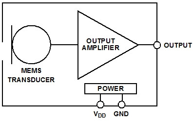 .
.Figure 1: Block diagram of a typical analog MEMS microphone.
Figure 2 is the functional block diagram of PDM output MEMS microphone, and Figure 3 is a typical I2S output digital microphone. The I2S microphone contains all of the PDM microphones, as well as decimation filters and serial ports.
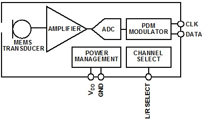
Figure 2: Typical PDMMEMS microphone block diagram
.jpg)
Figure 3: Typical I2SMEMS microphone block diagram
MEMS microphone package is unique in semiconductor devices because there is a hole in the package for acoustic energy to reach the transducer. Inside this package, MEMS microphone transducers are bound to analog or digital ASICs and installed on a common stack. Then a cover is bound above the stack to seal the transducer and ASIC. This stack is usually a small PCB, which is used to connect the signal from the IC to the pin outside the microphone package.
Figures 4 and 5 show the internal details of analog and digital MEMS microphones, respectively. In these pictures, you can see the left transducer and the right ASIC (under the epoxy resin), both of which are installed on the stack. The digital microphone has additional binding wires to connect the electrical signals from the ASIC to the stack.
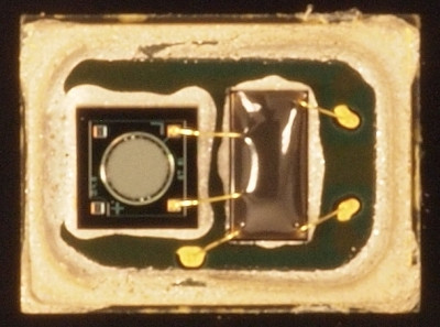
Figure 4: Transducer and ASIC in analog MEMS microphone
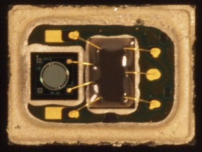
Figure 5: Transducer and ASIC in Digital MEMS Microphone
Analog microphone
The typical output impedance of an analog MEMS microphone is several hundred ohms. This impedance is higher than the low output impedance that the operational amplifier usually has, so you need to know the impedance of the signal chain immediately behind the microphone.
A low impedance circuit behind the microphone attenuates the signal level. For example, some codecs have a programmable gain amplifier (PGA) before ADC. In a high gain setting, the input impedance of the PGA may be only a few thousand ohms. A MEMS microphone with an output impedance of 200 Ω followed by a PGA with an input impedance of 2k Ω will attenuate the signal level by nearly 10%.
The output of an analog MEMS microphone is usually biased to a DC voltage value between the ground and the power supply voltage. The selection principle of this bias voltage is that the peak value of the amplitude output signal will not be clamped by the power supply voltage or ground potential limit. The existence of this DC bias voltage also means that the microphone is usually connected to the amplifier or converter chip behind it through AC coupling. The selection principle of the series capacitor is that the high pass filter circuit formed together with the input impedance of the codec or amplifier will not make the low frequency part of the signal roll off above the natural low frequency roll off of the microphone.
For a microphone with 100Hz low-frequency - 3dB point and a codec or amplifier with 10k Ω input impedance (both are common values), even a relatively small 1.0F capacitor will set the angular frequency of the high pass filter to 16Hz, which is far beyond the range that can affect the microphone response. Figure 6 shows an example of such a circuit, where an analog MEMS microphone is connected to an op amp in a in-phase configuration.
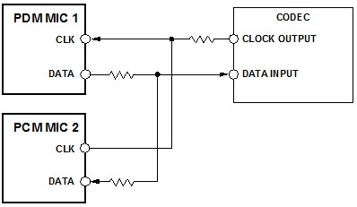

Figure 6: Analog microphone connected to in-phase op amp circuit
Digital microphone
Digital microphone transfers the A/D conversion function from the codec to the microphone, thus realizing the full digital audio capture channel from the microphone to the processor. Digital MEMS microphones are often used in applications where analog audio signals are susceptible to interference.
For example, in a tablet computer, the microphone may not be close to the ADC, and the signal between these two points may pass through or close to Wi Fi, Bluetooth or cellular antenna. After digitizing these connections, they will not be vulnerable to these RF interference to generate noise or distortion in the audio signal. This improvement in picking up harmful system noise provides great flexibility for microphone layout in design.
Digital microphones are also useful in systems that require only an analog audio interface to connect to an analog microphone. In systems that only need audio capture but do not need playback, such as surveillance cameras, the use of digital output microphones eliminates the need for separate codecs or audio converters, and microphones can be directly connected to digital processors.
Of course, good digital design experience must still be applied to the clock and digital signals of digital microphones. The small value source termination resistance of 20 Ω to 100 Ω is very useful, which can ensure good digital signal integrity for a few inch long cabling (Figure 7). When using a shorter routing length or running a digital microphone clock at a lower rate, the microphone pin can be directly connected to the codec or DSP without any passive components.
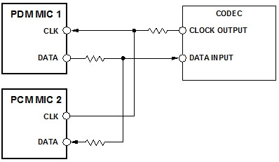

Figure 7: PDM Microphone Connected to Codec by Source Termination
PDM is a common digital microphone interface. This interface allows two microphones to share a common clock and data cable. Each microphone is configured to produce its own output at different edges of the clock signal. In this way, the outputs of the two microphones can be synchronized with each other, and the designer can ensure that the data from each channel is captured at the same time.
In a bad case, the data captured from two microphones may be separated by half a clock signal cycle in time. The typical frequency of this clock is about 3MHz, so the time difference in the channel is only 0.16us, which is far less than the threshold that the listener can perceive. This same synchronization mechanism can also be extended to systems with more than two PDM microphones. Just ensure that all microphones are connected to the same clock source and that data signals are filtered and processed together. In the case of analog microphones, this synchronization implementation will move up to the ADC.
I2S
I2S has been a universal digital interface for audio converters and processors for many years, but it has only recently been integrated into devices at the edge of the signal chain, such as microphones. The I2S microphone has the same system design advantages as the PDM microphone, but it no longer outputs the PDM signal with high sampling rate. The digital data it outputs uses the sampled baseband audio sampling rate. In the PDM microphone scheme, this extraction is implemented in the codec or DSP, but in the I2S microphone scheme, this extraction process is directly completed in the microphone, so in some systems, ADC or codec can be completely canceled.
The I2S microphone can be directly connected to a DSP or (Figure 8) with this standard interface. Like the PDM microphone, two I2S microphones can be connected to a common data line. However, unlike the PDM, the I2S format uses two clock signals - a word clock and a bit clock.
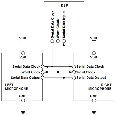

Figure 8: Stereo I2S microphone connected to DSP
When size is important
In general, the package size of analog MEMS microphones is smaller than that of digital microphones. This is because the analog microphone package requires fewer pins (generally three, while the digital microphone requires five or more), and the analog preamplifier circuit is also less than the digital one. Therefore, the analog preamplifier manufactured by the same manufacturing process is smaller than the digital preamplifier. In most space constrained designs, such as many small mobile devices, analog microphones are more popular because of their small size.
The package size of the analog microphone can be 2.5 × three point three five × 0.88mm or less, while the package size of PDM microphone is usually 3 × four × 1mm, the package volume is increased by 62%.
Analog and digital MEMS microphones can play their own advantages in different applications. Considering the limitations of system volume and component layout, electrical connection, potential noise sources and interference, we can make a decision on the microphone suitable for the current design.
|
Disclaimer: This article is transferred from other platforms and does not represent the views and positions of this site. If there is any infringement or objection, please contact us to delete it. thank you! |


