Detailed Knowledge of Parasitic Capacitors
Time:2022-10-20
Views:1692
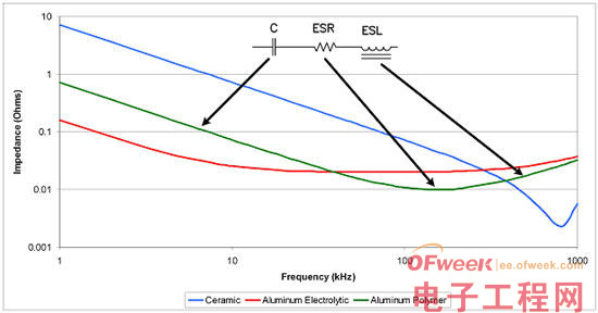
Power ripple and transient specifications will determine the size of the required capacitor, and also limit the parasitic composition settings of the capacitor. Figure 1 shows the basic parasitic composition of a capacitor, which is composed of equivalent series resistance (ESR) and equivalent series inductance (ESL), and shows the relationship between the impedance and frequency of three kinds of capacitors (ceramic capacitor, aluminum electrolytic capacitor and aluminum polymer capacitor) in a curve. Table 1 shows the values used to generate these curves. These values are typical of low voltage (1V~2.5V) and medium current (5A) synchronous step-down power supply.


Table 1: Comparison of three capacitors, each with advantages.
At low frequencies, all three capacitors do not exhibit parasitic components, because impedance is obviously only related to capacitance. However, the impedance of aluminum electrolytic capacitors stopped decreasing and began to show resistance characteristics at relatively low frequencies. This resistance characteristic continues to increase until a relatively high frequency is reached (capacitor inductance). Aluminum polymer capacitor is another kind of capacitor that does not conform to the ideal condition. Interestingly, it has a low ESR, and the ESL is obvious. Ceramic capacitors also have low ESR, but because of their smaller housing size, their ESL is smaller than that of aluminum polymer and aluminum electrolytic capacitors.

Figure 1: Different Impedance Changes of Parasitics on Ceramic, Aluminum and Aluminum Polymer Capacitors
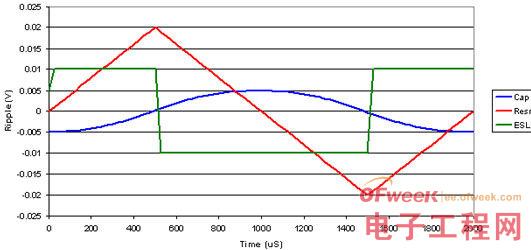
Figure 2 shows the simulated power output capacitor waveform of the continuous synchronous regulator operating at 500 kHz. It uses the main impedance of the three capacitors shown in Figure 1: ceramic capacitor; Aluminum ESR; Aluminum polymer ESL
The red line is aluminum electrolytic capacitor, which is dominated by ESR. Therefore, the ripple voltage is directly related to the ripple current of the inductor. The blue line represents the ripple voltage of the ceramic capacitor, which has small ESL and ESR. In this case, the ripple voltage is a component of the ripple current of the output inductor. Since the ripple current is linear, this results in a series of square parts of time, and the shape looks like a sinusoidal curve.
Finally, the green line represents ripple voltage, and its capacitor impedance is dominated by its ESL, such as aluminum polymer capacitor. In this case, the output filter inductance and the ESL form a voltage divider. The relative phase of these waveforms is as expected. When the ESL is dominant, the ripple voltage guides the inductance current of the output filter. When ESR dominates, the ripple is in phase with the current, while when capacitor dominates, it is delayed. In reality, the output ripple voltage does not contain only the voltage from one of these elements. Instead, it is the sum of all three component voltages. Therefore, some parts can be seen in the ripple voltage waveform.

Figure 2: Capacitor and its parasitic elements form different ripple voltages in the continuous synchronous step-down regulator
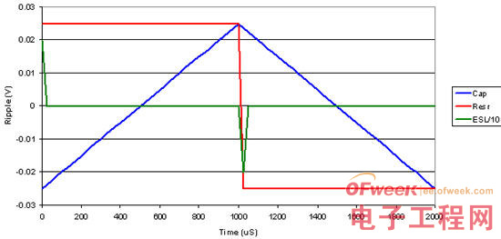
Figure 3 shows the waveform of a deep continuous flyback or step-down regulator, whose output capacitor current can be positive and negative, and the specific state will change rapidly. The red line clearly indicates this situation, and its voltage is obtained by multiplying this current by ESR, and the result is a square wave. The voltage of capacitor element is a component of square wave. It causes linear charging and discharging, as shown in the blue triangle waveform. Finally, the voltage of capacitor ESL is obvious only when the current changes during the transition. This voltage can be very high, depending on the rise time of the output current. Note that in this case, the green line is divided by 10 (assuming a 25 nS current transition). These large inductance spikes are one of the reasons why two-stage filters often appear in flyback or buck power supplies.

Figure 3: Waveform changes with continuous flyback or step-down output current
In conclusion, the impedance of the output capacitor is helpful to improve the ripple and transient performance. With the increase of power frequency, the influence of parasitic problems is greater and should not be ignored. Near 20kHz, the ESR of aluminum electrolytic capacitor is large enough to dominate the capacitance impedance. At 100kHz, some aluminum polymer capacitors show inductance. When the power supply enters the megahertz switching frequency, please pay attention to the ESL of all three capacitors
|
Disclaimer: This article is transferred from other platforms and does not represent the views and positions of this site. If there is any infringement or objection, please contact us to delete it. thank you! |


