Simplify AC to DC conversion with transformer and LDO
Time:2022-09-08
Views:1783
When creating industrial power supply, a common challenge is to convert AC voltage power supply to DC voltage power supply. Almost all applications need to change AC voltage to DC voltage, from charging mobile phones to powering microcontrollers of microwave ovens. Generally speaking, this conversion is performed by using a transformer and a rectifier, as shown in Fig. 1. In this circuit, the voltage is reduced by a transformer (one time the ratio of turns of the primary and secondary windings of the transformer).


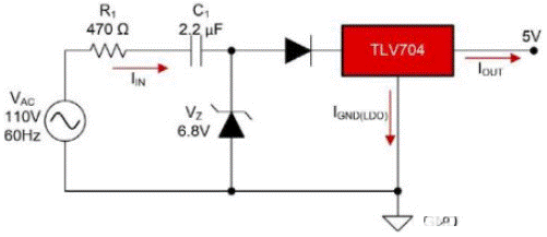
Figure 2: basic capacitive voltage drop circuit with LDO for 110 VAC, 5 VDC and 30 Ma


Figure 1: simplified AC to DC conversion using transformers and LDOS
Magnetic solutions have several disadvantages. You may know that transformers work by converting magnetic flux into current. Due to this conversion, the transformer will generate a lot of electromagnetic interference (EMI). The output voltage of the transformer is also extremely noisy, which requires a large capacitance to filter out noise. For low-power applications, a simpler and cost-effective method can be used to eliminate magnetic elements. Just as two resistors form a voltage divider, you can use capacitors to generate AC impedance (reactance), which reduces the voltage before it reaches the power supply. This configuration is commonly referred to as a capacitive voltage drop solution.
When the load is not connected, the basic capacitor voltage drop solution requires the zener diode to absorb the current required for the application. This zener diode is required, so the input voltage of the linear regulator (LDO) will not exceed the rated value.

Figure 2: basic capacitive voltage drop circuit with LDO for 110 VAC, 5 VDC and 30 Ma
A disadvantage of the capacitive voltage drop topology is that it is not efficient because a lot of power will dissipate with the heat of the resistor and LDO. Even if the LDO is not regulated, the efficiency is still not ideal due to the energy consumed in the zener diode.
To improve the efficiency of the system, you need to optimize the voltage drop of three main components - surge resistance, zener diode and LDO. Formula 1 shows how to calculate the efficiency of the basic capacitance voltage drop solution shown in Fig. 2.
Since capacitive voltage drop solutions are common power configurations in industrial applications such as electronic metrology and factory automation, Ti has developed a component that focuses on optimizing the efficiency of capacitive voltage drop architecture and the size of the solution. Tps7a78 integrates many discrete components needed to realize capacitive voltage drop circuits, such as active bridge rectifiers. Tps7a78 is specially designed for the use of capacitive voltage drop circuits, which can integrate a variety of functions and improve the overall system efficiency. For example, tps7a78 integrates a switched capacitor stage, which can reduce the input voltage by four times, thereby reducing the input current at the same rate, and helping to use a smaller capacitance drop capacitance. This feature can achieve a smaller solution size, reduce system cost and reduce standby power consumption.

Figure 3: 30mA capacitor voltage drop solution at 30mA using tps7a78
To understand the efficiency of using tps7a78 in capacitive voltage degradation and linear regulator, we can compare the traditional solution shown in Fig. 2 with the tps7a78 solution shown in Fig. 3. In the traditional voltage drop solution using a linear regulator, the efficiency of the system is 11%. When configured to supply power to the same load, the tps7a78 can achieve 40% efficiency because the input current of the switching capacitor is reduced and smaller surge resistance is required.
|
Disclaimer: This article is transferred from other platforms and does not represent the views and positions of this site. If there is any infringement or objection, please contact us to delete it. thank you! |


